36
07610-003-78-18-N
1
3
2
4
2
5
6
7
8
2
6
ITEM
QTY
DESCRIPTION
PART NUMBER
1
1
Strainer, Inlet, 1/2"
04730-217-01-10
2
3
Nipple, 1/2" Close, Brass
04730-207-15-00
3
1
Tee, Brass, 1/2" x 1/2" x 1/2"
04730-211-27-00
4
1
Regulator, 1/2"
04820-100-04-07
5
1
Valve, 1/2" NPT Brass, 24VDC Coil
04810-003-75-16
6
2
Hose, 1/2" x 42" S/S Braided w/PTFE, Male Swivel
04720-003-76-09
7
1
Bracket, Inlet Plumbing Support
05700-003-74-42
8
1
Bracket, Upper Inlet Plumbing Support
05700-003-74-86
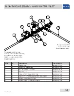
The opposite end of this hose
connects to the Final Rinse Assembly.
For units with the Booster Heater
Option, this hose connects to the
Booster Heater Inlet.
The opposite end of this
hose connects to the
Wash Tank Fill Assembly.
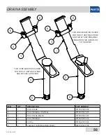
PLUMBING ASSEMBLY, MAIN WATER INLET
PARTS
Summary of Contents for CREW 44
Page 2: ......
Page 6: ......
Page 81: ...72 07610 003 78 18 N STEAM BOOSTER HEATER SCHEMATICS ...
Page 84: ...75 07610 003 78 18 N 208 230 460 VOLT 60 HZ 3 PHASE 44 ELECTRICALLY HEATED SCHEMATICS ...
Page 85: ...76 07610 003 78 18 N 208 230 VOLT 60 HZ 1 PHASE 44 ELECTRICALLY HEATED SCHEMATICS ...
Page 86: ...77 07610 003 78 18 N 208 230 460 VOLT 60 HZ 3 PHASE 44 STEAM HEATED SCHEMATICS ...
Page 87: ...78 07610 003 78 18 N 208 230 VOLT 60 HZ 1 PHASE 44 STEAM HEATED SCHEMATICS ...
Page 88: ...79 07610 003 78 18 N 208 230 460 VOLT 60 HZ 3 PHASE 66 ELECTRICALLY HEATED SCHEMATICS ...
Page 89: ...80 07610 003 78 18 N 208 230 VOLT 60 HZ 1 PHASE 66 ELECTRICALLY HEATED SCHEMATICS ...
Page 90: ...81 07610 003 78 18 N 208 230 460 VOLT 60 HZ 3 PHASE 66 STEAM HEATED SCHEMATICS ...
Page 91: ...82 07610 003 78 18 N 208 230 VOLT 60 HZ 1 PHASE 66 STEAM HEATED SCHEMATICS ...
Page 92: ...83 07610 003 78 18 N BLOWER DRYER 240V SCHEMATICS ...
Page 93: ...84 07610 003 78 18 N BLOWER DRYER 480V SCHEMATICS ...


