background image

85

85

Jackson WWS, Inc. • 6209 N. US Hwy 25E • Gray, KY 40734 USA

1.888.800.5672 • www.jacksonwws.com

CREW

® 

Manual • Rev N • 07610-003-78-18 • Issued: 07-27-10 • Revised: 8-22-16

Summary of Contents for CREW 44

Page 1: ...CREW CREW Manual Rev N 07610 003 78 18 Issued 07 27 10 Revised 8 22 16 INSTALLATION OPERATION AND SERVICE MANUAL CREW SERIES CONVEYOR DISHMACHINES ...

Page 2: ......

Page 3: ...improper installation if serial number has been removed or altered or if unit is used for a purpose other than originally intended TRAVEL LIMITATIONS Jackson WWS limits warranty travel time to 2 two hours and mileage to 100 one hundred miles Jackson WWS will not pay for travel time and mileage that exceeds this or any additonal fees such as those for air or boat travel without prior authorization ...

Page 4: ...s G 10 27 14 KAP QOF 386 Added new Vent Shield P N 05700 004 18 73 on pg 54 H 03 02 15 KAP N A Updated P N for item 10 on pg 55 J 03 10 15 KAP N A Updated P N for item 4 on pg 71 K 04 17 15 KAP N A Updated Rinse Assembly Drawing on pg 41 L 05 26 15 KAP N A Combined PLC 1 2 under part 06401 004 13 59 M 01 25 16 JH N A Added Hatco Booster service information to page 61 Updated manual format Added Ex...

Page 5: ...nce data plate important note i caustic chemicals ABBREVIATIONS ACRONYMS ANSI American National Standards Institute CFM Cubic Feet per Minute GHT Garden Hose Thread GPM Gallons per Minute GPG Grains per Gallon HP Horse Power Hz Hertz ID Inside Diameter kW Kilowatts NFPA National Fire Protection Association NPT National Pipe Thread PSI Pounds per Square Inch GUIDES ...

Page 6: ......

Page 7: ...ur technical support staff Please have this manual with you when you call so that our staff can refer you if necessary to the proper page Technicalsupportisnotavailable on holidays Contact technical support toll free at 1 888 800 5672 Technical support is available for service personnel only ELECTRICALLY HEATED MODELS CREW 44 CREW 66 Chemical sanitizing rack conveyer machine STEAM HEATED MODELS CR...

Page 8: ...roubleshooting 24 PARTS Control Box Components 26 Overloads 28 Miscellaneous Electrical Components 29 Wash Heater Heater Shroud Assemblies 30 Pump Suction Assembly 31 Wash Heaters 32 Door Assembly 33 Pre Wash Door Assembly 34 Door Spring Assembly 35 Plumbing Assembly Main Water Inlet 36 Wash Tank Fill Assembly 37 Pre Wash Tank Fill Assemblies 38 Wash Manifold Arm Assembly 39 Pre Wash Manifold Arm ...

Page 9: ...bly 66 Blower Dryer Option Control Box 67 Blower Dryer Option Blower Assembly 68 SCHEMATICS Booster Heater 3 Phase 69 Booster Heater 1 Phase 12kW 70 Booster Heater 1 Phase 18kW 71 Steam Booster Heater 72 Temperature Board 73 Photocell Table Limit Switch 74 44 208 230 460V 60Hz 3 Phase 75 44 208 230V 60Hz 1 Phase 76 44 Steam 208 230 460V 60Hz 3 Phase 77 44 Steam 208 230V 60Hz 1 Phase 78 66 208 230 ...

Page 10: ... in 7 3 8 in RA SAN E2 E1 W 23 3 4 in 23 3 4 in 23 3 4 in 33 4 in 171 8 in DET DET S W E2 E1 C SAN 2 1 4 in RA 26 5 8 in D 7 7 8 in 19 1 8 in 111 2 in 11 1 2 in 441 8 in NOTE 2 VENTILATION DUCT ADAPTERS ARE ADJUSTABLE FROM 51 1 2 TO 54 NOTE 1 THE MAXIMUM DOOR HEIGHT MAY BE REDUCED BY THE ADDITION OF OPTIONAL DOOR BRACKETS MAXIMUM HEIGHTS OF 91 89 87 ARE AVAILABLE NOTE 3 THE DRIVE ASSEMBLY AND GUAR...

Page 11: ...HE UNIT INSTALLATION ON THE UNLOAD END IS STANDARD IF INSTALLED ON THE LOAD END PLEASE ENSURE ANY SCRAP SINKS IN THE TABLING ARE AT AN ADEQUATE DISTANCE TO PROVIDE FOR CLEARANCE OF THE DRIVE ASSEMBLY NOTE 4 ALL VERTICAL DIMENSIONS MAY VARY DUE TO THE ADJUSTABLE FEET 16 in 4 in 441 8 in V2 V1 44 RIGHT TO LEFT Applies to steam heated units Chemical sanitizing units only 44 MACHINE DIMENSIONS SPECIFI...

Page 12: ... in MAX NOTE 1 3 8 in 9 in 2 1 4 in 14 7 8 in 21 1 2 in 26 5 8 in 30 5 8 in TABLE to TABLE 66 in 851 2 in 14 in 16 5 8 in 20 3 8 in 14 7 8 in W2 W3 W1 SAN D1 C S RA D2 E1 E2 W3 W2 E1 E2 W1 RA SAN V1 V2 S DET D1 C CP D2 E1 E2 W1 CP 661 8 in DET 16 in 4 in 71 5 8 in 101 8 in NOTE 3 NOTE 1 THE MAXIMUM DOOR HEIGHT MAY BE REDUCED BY THE ADDITION OF OPTIONAL DOOR BRACKETS MAXIMUM HEIGHTS OF 91 89 87 ARE...

Page 13: ... 73 1 2 TO 76 NOTE 1 THE MAXIMUM DOOR HEIGHT MAY BE REDUCED BY THE ADDITION OF OPTIONAL DOOR BRACKETS MAXIMUM HEIGHTS OF 91 89 87 ARE AVAILABLE NOTE 4 ALL VERTICAL DIMENSIONS MAY VARY DUE TO THE ADJUSTABLE FEET 66 RIGHT TO LEFT Applies to steam heated units Chemical sanitizing units only Pre wash cold water thermostat option only E1 MAIN ELECTRICAL CONNECTION 1 375 DIA HOLE E2 BOOSTER HEATER ELECT...

Page 14: ...DE LOADER DRAIN HOSE SIDE LOADER DRAIN HOSE 23 L R UNHOODED SIDE LOADER 23 R L UNHOODED SIDE LOADER VENTILATION SCOOP VENTILATION SCOOP VENTILATION COWL WITH CUTOUT FOR R L UNITS VENTILATION COWL WITH CUTOUT FOR L R UNITS DIMENSION IS 30 00 FOR THE 30 UNHOODED SIDE LOADER DIMENSION IS 30 00 FOR THE 30 UNHOODED SIDE LOADER ELECTRICAL CONDUIT ELECTRICAL CONDUIT SPECIFICATIONS SIDE LOADER DIMENSIONS ...

Page 15: ... in 201 4 in W1 S W2 PS PW 33 69 11 3 8 in 22 in 71 2 in E E E E MAIN ELECTRICAL CONNECTION 7 8 DIA HOLE W1 MAIN INLET WATER CONNECTION 3 4 NPT F W2 WATER OUTLET CONNECTION 3 4 NPT F PW WATER PRESSURE RELIEF OUTLET 3 4 NPT F PS STEAM PRESSURE RELIEF OUTLET 1 NPT F S STEAM SUPPLY TO BOOSTER 1 NPT F C STEAM CONDENSATE CONNECTION 3 4 NPT F STEAM BOOSTER HEATER DIMENSIONS SPECIFICATIONS ...

Page 16: ... Clearance 5 Height 19 75 Width 21 Shipping Weight 750lbs Shipping Size Length 77 Depth 41 Height 89 124 06 48 07 25 50 9 00 ELECTRICAL CONNECTION 25 50 9 00 ELECTRICAL CONNECTION 48 07 102 07 WITH 44 DISHMACHINE WITH 66 DISHMACHINE SPECIFICATIONS BLOWER DRYER OPTION DIMENSIONS ...

Page 17: ...35 6 35 6 Pre Wash Tank N A 15 8 N A 15 8 Electrical Loads as applicable Wash Motor HP 3 0 3 0 3 0 3 0 Drive Motor HP 0 25 0 25 0 25 0 25 Pre Wash Motor HP N A 2 0 N A 2 0 Wash Heater kW 15 or 18 18 N A N A OPERATING PARAMETERS SPECIFICATIONS NOTE Always refer to the machine data plate for specific electrical and water requirements The material provided on this page is for reference only and may c...

Page 18: ...Wash Temperature 120 120 120 120 Minimum Rinse Temperature 120 120 120 120 Incoming Water Temperature 12 kW Booster 80 80 N A N A 18 kW Booster 50 50 N A N A No Booster 120 120 120 120 Other Water Requirements Water Flow Pressure PSI 15 15 15 15 Flow Rate Minimum GPM 1 27 1 18 1 27 1 18 Water Line Size NPT 1 2 1 2 1 2 1 2 Drain Line Size NPT 1 1 2 1 1 2 1 1 2 1 1 2 Steam Requirements Steam Line fo...

Page 19: ...r 208 230 or 460 Volts Some of the heating elements used in our machines are actually rated for other voltages such as 240 or 480 Volts Always verify the amperage draw of the machine in operation when sizing circuit protection If the machine is equipped with the optional rinse heater note the rinse heater has its own electrical connection and therefore requires a separate service Amperage loads fo...

Page 20: ...60 10 0 1 8 86 5 98 3 230 1 60 10 0 1 8 71 9 83 7 240 1 60 10 0 1 8 75 0 86 8 208 3 60 8 6 1 1 50 0 59 7 230 3 60 8 4 1 1 41 5 51 0 240 3 60 8 4 1 1 43 4 52 9 460 3 60 4 2 0 6 20 8 25 6 480 3 60 4 2 0 6 21 7 26 5 44 with 18 kW Wash Heater Volts Phase Freq Wash Motor Amps Drive Motor Amps Total Load 208 1 60 10 0 1 8 11 8 230 1 60 10 0 1 8 11 8 208 3 60 8 6 1 1 9 7 230 3 60 8 4 1 1 9 5 460 3 60 4 2...

Page 21: ...10 0 1 8 21 2 208 3 60 6 8 8 6 1 1 16 5 230 3 60 6 4 8 4 1 1 15 9 460 3 60 3 2 4 2 0 6 8 0 66 Steam Denotes 240 volt heating elements that have been down rated when 230 volts is applied Denotes 480 volt heating elements that have been down rated when 460 volts is applied Volts Phase Freq Rinse Heater Amps 208 1 60 57 7 230 1 60 47 9 208 3 60 33 3 230 3 60 27 7 460 3 60 13 8 40 F Rise 12 kW Booster...

Page 22: ... territorial and national codes The installing plumber is responsible for ensuring the incoming water lines are flushed of debris before connecting to the machine Note that chips and materials from cutting processes can become lodged in the solenoid valves and prevent them from opening or closing Any valves that are found to be fouled or defective because of foreign matter left in the water line a...

Page 23: ...chine voltage total amperage load and serial number If a data plate has been damaged and cannot be read contact the manufacturer The main power terminal blocks for the dishmachine and for the rinse booster heater if applicable are located at the top of the machine Remove the top cover to access these connections Route incoming power lines within conduit that will connect via fittings to the pre pu...

Page 24: ...CHEMICAL SUPPLY FEEDER SYSTEM For the dishmachine to operate correctly connect it to a third party chemical dispenser that meets the requirements of NSF Standard 29 Contact a chemical supplier about connecting a dispenser to the dishmachine Chemical dispensers must be set for the type and concentration of chemicals being used Detergent usage and water hardness are two factors that contribute great...

Page 25: ... BOOSTER HEATER ELECTRICAL CONNECTION OPENING 1 375 SHOWN FROM REAR OF LEFT TO RIGHT UNIT RIGHT TO LEFT UNIT IS MIRRORED DETERGENT INJECTION POINT ANOTHER BULKHEAD PLUG IS PROVIDED ON THE LEFT SIDE OF THE UNIT ADJUSTABLE BULLET FEET 1 1 2 NPTF DRAIN CONNECTION BULKHEAD OPENING FOR CONDUCTIVITY PROBE INSTRUCTIONS INSTALLATION ...

Page 26: ...RING REMOVE THIS JUMPER WIRE TO ALLOW FOR TABLE LIMIT SWITCH CONNECTIONS VENT FAN DETERGENT DISPENSER RINSE AID SANITIZER FROM DOOR SWITCH TABLE LIMIT SWITCH CONNECTION CONNECTION POINTS FOR EXTERNAL DEVICES 115v AC Secondary Control Transformer Signal NOTE Vent Fan wiring is shown All external devices are wired similarly Wiring Diagram Terminal Board Vent Fan CREW Dishmachine Contactor Supplied b...

Page 27: ...L S L L XL Load Unload 66 Right to Left XL L L S L S XL Load Unload IMPORTANCE OF PROPER CURTAIN PLACEMENT The curtains inside the dishmachine must be installed properly for the machine to operate correctly Curtains are used to control air currents inside the unit and assist in maintaining the heat necessary to keep energy costs down Note the approximate locations for each type of curtain in the a...

Page 28: ... might be required in some areas Turn off the power supply and place the dishwasher disconnect if applicable in the off position Lockout tag out to prevent the power supply from being turned back on accidentally Failure to install this kit within the guidelines might adversely affect safety performance component life and warranty coverage Do NOT pull power for the Drain Quench Assembly from the ma...

Page 29: ...water to inlet side of solenoid valve DRAIN QUENCH SYSTEM IF THERE ARE ANY ISSUES AFTER INSTALLATION PLEASE CONTACT TECHNICAL SERVICE AT 1 888 800 5672 5 Secure all electrical ensure connection is to 120V facility power and plumbing connections 6 Restore water and power to the machine and verify drain quench performance Power cannot be taken from the machine CAUTION ...

Page 30: ...at is placed in the unit will typically reduce the temperature of the wash tank and the first rack might need to run through the unit again This process may be necessary any time the unit has not been operated for an extended period of time although this is dependent on the type of ware being used its temperature and the ambient temperature of the kitchen area To ensure proper operation always obs...

Page 31: ...nt operation of the unit by removing soil and debris that might other wise become trapped in nozzles or deposited onto ware Curtains should be removed and scrubbed with mild detergent and a brush and allowed to air dry Strainers should be removed and debris scooped out Do not hit strainers to remove debris this can cause them to warp and not seat correctly Rinsing the strainer under water should r...

Page 32: ...or 5 minutes 7 Inspect the inside of the unit to determine if expectations have been met If not try running the delime solution through the unit for more time 8 Once clean drain the machine completely 9 Close the door 10 Refill the unit 11 Press the START button and run the unit in Manual for 10 minutes 12 Press the START button to turn off the unit 13 Open the front door 14 Drain the unit 15 Flip...

Page 33: ...illustration below for the designation of each LED PLC1 is used for the 44 Electric and Steam units An expansion PLC PLC2 is used in conjunction with PLC1 for 66 Electric and Steam units Inputs correspond to the connections behind the top flip up panel of the PLC and are marked I1 through I8 Outputs correspond to the connections behind the bottom flip up panel of the PLC and are marked Q1 through ...

Page 34: ...USED 4 NOT USED 5 NOT USED 6 NOT USED 7 NOT USED 8 NOT USED OUTPUTS 1 PRE WASH TANK FILL SOLENOID 2 PRE WASH MOTOR CONTACTOR 3 NOT USED 4 NOT USED 5 NOT USED 6 NOT USED 7 N A 8 N A INPUTS 1 On Off Switch 2 Door Switch Safety Interlocks 3 Rack Inlet Switch 4 Final Rinse Switch 5 Lower Wash Float Switch 6 Upper Wash Float Switch 7 Manual Delime Switch 8 Side Loader Switch on with no rack present OUT...

Page 35: ...C3 TB1 C2 C1 TB2 PLC2 PLC1 T2 T1 8 9 1 HC1 TB3 TB4 3 2 3 4 6 5 7 1MOL 3MOL 2MOL R1 R2 R3 R4 R5 R6 13 TB5 All operational relays use green LED indicating lights to verify proper operation These relays are mounted immediately to the right of the motor contactors Please refer to the illustration at right R1 R2 R3 R4 R5 LED The illustration above depicts the components of a 66 electrically heated unit...

Page 36: ...OL 1 Overload Pre Wash Motor Used on 3 Phase 66 Units See Overload Page TB1 1 Terminal Board Signal 05940 003 77 43 TB2 1 Terminal Board DC 05940 003 77 65 TB3 1 Terminal Board L1 05940 021 94 85 TB4 1 Terminal Board L2 05940 021 94 85 TB5 1 Terminal Board Blower 05940 021 70 74 1 1 Terminal Block 3 Pole 05940 011 48 27 2 1 Fan 24VDC 05999 002 47 12 3 2 Fan Finger Guard 05999 003 12 92 4 1 Ground ...

Page 37: ...ified for 3 phase units only For GE brand MT03 series overloads the process for setting is as follows Determine the Full Load Amps for the drive motor Set the overload at the closest setting without going over for the FLA of the motor The overload already compensates for the FLA and will have a set point that is 125 of the FLA Example Drive motor is rated at 1 0 FLA on the data plate The replaceme...

Page 38: ...394 05975 011 49 03 Clamp 1 Conduit 05975 003 77 88 Clamp 3 4 Conduit 05975 003 77 89 Plug 2 5 Hole Louvered 05975 003 77 39 Plug 05975 011 47 81 Plug 05975 002 29 94 Plug 05340 044 46 79 Plug 05975 011 59 49 Bushing 05975 003 10 46 Grommet 1 250 OD x 1 000 ID 05975 111 58 01 Grommet 7 8 Split 05975 200 40 00 Start Switch 05930 003 76 52 Proximity Switch 24VDC 05930 003 76 51 Delime Switch 05930 3...

Page 39: ...4 1 Gasket Pump Suction 05330 003 75 87 5 1 Gasket Heater 05330 200 02 70 6 1 Heater Box Rails 05700 003 74 72 7 1 Wash Pump Suction Weldment 05700 003 77 63 8 2 Washer S S 05311 174 01 00 9 9 Locknut 1 4 20 Hex w Nylon Insert 05310 374 01 00 10 6 Nut Hex 5 16 18 S S 05310 275 01 00 11 6 Lockwasher 5 16 Split S S 05311 275 01 00 12 1 Wash Heating Element 15kW 18kW See Heater Chart WASH HEATER HEAT...

Page 40: ...asket Suction Casting 05330 003 75 89 2 1 Gasket Pump Suction 05330 003 75 87 3 1 Pre Wash Pump Suction Weldment 05700 003 82 27 4 1 Strainer Pre Wash Pump 05700 003 81 28 USED ON ALL PRE WASH TANKS AND ALL STEAM HEATED TANKS 4 1 3 2 PARTS PUMP SUCTION ASSEMBLY ...

Page 41: ...1 79 31 05945 003 75 02 460 3 18 04540 121 79 32 05945 003 75 02 SERVICE NOTES When replacing wash heaters it is highly recommended to change the gasket also Once installed gaskets become compressed and are subject to extreme temperature changes Replacing the gasket with the heater may prevent future leaks The nuts used to secure the heater to the casting should be torque to 16 in lbs After tighte...

Page 42: ...38 PART N DESCRIPTION QTY ITEM 05700 0 F BRACKET DOOR GUIDE 2 1 09330 0 DOOR GUIDE 2 2 05700 0 W DOOR WELDMENT 44 1 3 09330 0 END PIECE DOOR RIGHT SIDE 1 4 09330 0 END PIECE DOOR LEFT SIDE 1 5 05700 0 W DOOR STOP SUPPORT WELDMENT 1 6 05310 3 NUT LOCK 1 4 20 HEX W NYLON INSERT 32 7 05305 0 SCREW 1 4 20 X 1 82 C SINK PHILLI 10 8 05305 0 SCREW 10 32 X 1 PHILLIPS PAN HD 26 9 05930 0 MAGNET 217310 NEO ...

Page 43: ...5700 003 82 46 12 2 Locknut 6 32 Hex w Nylon Insert 05310 373 03 00 13 1 Cover Door Magnet 05700 004 07 38 DESCRIPTION QTY ITEM F BRACKET DOOR GUIDE 2 1 DOOR GUIDE 2 2 W DOOR WELDMENT 22 PRE WASH 1 3 END PIECE DOOR RIGHT SIDE 1 4 END PIECE DOOR LEFT SIDE 1 5 W DOOR STOP SUPPORT WELDMENT L R 1 6 LOCKNUT 1 4 20 HEX W NYLON INSERT 30 7 SCREW 1 4 20 X 1 82 C SINK PHILLI 10 8 SCREW 10 32 X 1 PHILLIPS P...

Page 44: ... NUMBER 1 1 Casting Door Spring Mount 09515 003 73 78 2 1 Spring Door 05315 002 67 29 3 2 Spindle Door Spring 05700 002 67 28 4 1 Pin Door Spring 05700 002 83 55 5 1 Door Spring Bracket Weldment 05700 003 74 10 6 2 Washer 1 4 S S 05311 174 01 00 7 6 Locknut 1 4 20 Hex w Nylon Insert 05310 374 01 00 8 1 Cotter Pin 3 32 x 3 4 05315 207 01 00 PARTS DOOR SPRING ASSEMBLY ...

Page 45: ...4VDC Coil 04810 003 75 16 6 2 Hose 1 2 x 42 S S Braided w PTFE Male Swivel 04720 003 76 09 7 1 Bracket Inlet Plumbing Support 05700 003 74 42 8 1 Bracket Upper Inlet Plumbing Support 05700 003 74 86 The opposite end of this hose connects to the Final Rinse Assembly For units with the Booster Heater Option this hose connects to the Booster Heater Inlet The opposite end of this hose connects to the ...

Page 46: ... 06 23 3 1 Nipple 1 2 Close Brass 04730 207 15 00 4 1 Gasket Rinse Manifold 05330 003 75 91 5 1 Valve 1 2 NPT Brass 24VDC Coil 04810 003 75 16 6 1 Tube Weldment Tank Fill 05700 003 76 81 7 1 Tank Fill Injector Weldment 05700 003 76 84 8 2 Locknut 1 4 20 Hex w Nylon Insert 05310 374 01 00 The hose from the Main Water Inlet Plumbing connects to this solenoid valve PARTS WASH TANK FILL ASSEMBLY ...

Page 47: ...003 76 84 5 2 Elbow 90 Degree 1 2 Brass 04730 206 08 00 6 1 Vacuum Breaker 1 2 Vacuum Breaker Repair Kit 04820 003 06 13 06401 003 06 23 7 2 3 Nipple 1 2 Close Brass 04730 207 15 00 8 1 Tee 1 2 x 1 2 x 1 2 NPT Brass 04730 211 27 00 9 1 0 Plug 1 2 NPT Brass Removed for Cold Water Fill Option 04730 209 03 00 10 1 2 Valve 1 2 NPT Brass 24VDC Coil 04810 003 75 16 11 1 2 Hose 1 2 x 42 S S Braided w PTF...

Page 48: ...39 07610 003 78 18 N 1 2 4 5 4 6 7 13 8 9 14 14 10 11 11 10 12 14 13 3 Mechanical Pump Seal 05330 002 34 22 PARTS WASH MANIFOLD ARM ASSEMBLY ...

Page 49: ...Riser 05700 003 72 37 9 1 Wash Manifold Weldment Upper 05700 003 73 66 10 2 Wash Arm Weldment Right 05700 003 75 80 11 2 Wash Arm Weldment Left 05700 003 75 79 12 12 Cap Threaded 04730 603 12 00 13 3 O Ring Silicone 103 Dia 2 1 2 x 2 11 16 OD 05330 003 73 71 14 4 O Ring Silicone 139 Dia 2 1 4 ID x 2 1 2 OD 05330 003 73 72 PUMP MOTOR ASSEMBLY PART NUMBER Wash Pump 3HP 208V 60Hz 3 Phase 06105 003 76...

Page 50: ...16 15 9 8 11 16 13 9 12 8 9 12 8 11 14 16 8 10 10 7 9 8 15 16 5 4 4 3 8 ILLUSTRATES PARTS FOR A LEFT TO RIGHT PRE WASH ILLUSTRATES PARTS FOR A RIGHT TO LEFT PRE WASH Mechanical Pump Seal 05330 002 34 22 PARTS PRE WASH MANIFOLD ARM ASSEMBLIES ...

Page 51: ... 2 1 2 OD 05330 003 73 72 10 1 Casting Pre Wash Manifold 09515 003 77 22 11 1 Tube Manifold Riser 05700 003 81 53 12 1 Wash Manifold Weldment Upper 05700 003 81 76 13 1 Wash Arm Weldment Left 05700 003 75 79 14 1 Wash Arm Weldment Right 05700 003 75 80 15 1 Pre Wash Arm Weldment Lower 05700 003 80 96 16 4 Cap Threaded 04730 603 12 00 PUMP MOTOR ASSEMBLY PART NUMBER Pre Wash Pump 2HP 208V 60Hz 3 Ph...

Page 52: ...43 07610 003 78 18 N RINSE INJECTOR CONNECTIONS P PRESSURE SWITCH S SANITIZER R RINSE AID NOTE 1 NOTE 2 5 14 16 3 4 17 22 22 21 20 23 18 8 1 9 8 15 7 1 2 1 19 16 6 12 10 10 11 5 PARTS RINSE ASSEMBLY ...

Page 53: ...56 10 2 Plug 1 8 NPT Brass 04730 209 07 37 11 1 Gasket Rinse Manifold 05330 003 75 91 12 1 Fitting Imperial Brass 05310 924 02 05 13 1 Plug 1 4 04730 209 01 00 14 3 O Ring Silicon 103 Dia 11 16 x 7 8 OD 05330 003 77 82 15 1 Elbow Brass 90 Deg 1 4 NPTM x 1 4 NPTF 04730 003 77 83 16 6 Locknut 1 4 20 Hex w Nylon Insert 05310 374 01 00 17 2 Bolt 1 4 20 x 1 2 Long 05305 274 02 00 18 2 Lockwasher Spring...

Page 54: ...1 6 3 4 3 5 TYPICAL PAWL DOG WITH HARDWARE ITEM QTY DESCRIPTION PART NUMBER 1 1 Pawl Bar Weldment 44 Units 05700 031 72 77 2 1 Pawl Bar Weldment 66 Units 05700 003 89 34 3 24 44 36 66 Spacer Pawl Bar Dog 05700 011 71 45 4 12 44 18 66 Pawl Bar Dog Casting 09515 021 69 00 5 12 44 18 66 Locknut 3 8 16 w Nylon Insert 05310 011 72 55 6 12 44 18 66 Bolt 3 8 16 x 1 3 4 Long 05306 011 36 94 PARTS PAWL BAR...

Page 55: ... 20 x 1 3 4 Hex Head 05305 274 10 00 3 8 Locknut 1 4 20 Hex w Nylon Insert 05310 374 01 00 4 6 Washer S S 05311 174 01 00 5 2 Roller Bracket Rod 05700 011 68 16 6 2 Shaft Roller 3 8 x 1 13 05700 011 68 14 Pawl Bar Roller Replacement Kit comes with 2 3 5 6 06401 003 11 80 2 6 5 3 3 4 1 5 2 PAWL BAR ASSEMBLIES PARTS ...

Page 56: ...T NUMBER 1 1 Top Guide Block 05700 011 69 49 2 1 Bottom Guide Block 05700 011 69 50 3 1 Pawl Bar Gutter Weldment 05700 021 66 86 4 1 Drive Gutter Gasket not shown 05330 011 68 55 1 Gutter Weldment Replacement Kit w Hardware 06401 003 09 95 1 Guide Block Replacement Kit 06401 003 10 15 3 1 2 PARTS PAWL BAR GUTTER ASSEMBLY ...

Page 57: ...74 82 3 2 Screw 1 4 20 x 7 8 S S 05305 274 05 00 4 2 Locknut 1 4 20 Low Profile w Nylon Insert 05310 374 02 00 5 1 Locknut 1 4 20 Hex w Nylon Insert 05310 374 01 00 6 1 Screw 1 4 20 x 2 3 4 Hex Head 05305 003 31 63 7 1 Magnet 05930 003 31 63 8 1 Wash Rinse End Cap 05700 011 60 92 1 Rack Paddle Assembly 05700 003 76 74 RACK PADDLE ASSEMBLY PARTS ...

Page 58: ...5700 003 81 91 05700 003 81 96 2 1 Stud 1 4 20 x 8 50 Long S S Double Ended Thread 05306 003 76 31 3 2 Locknut 1 4 20 Hex w Nylon Insert 05310 374 01 00 4 2 Locknut 1 4 20 Low Profile w Nylon Insert 05310 374 02 00 5 4 Screw 1 2 20 x 7 8 Hex Head S S 05305 274 05 00 6 4 Magnet 05930 003 31 63 7 1 End Cap 05700 011 60 92 8 1 Bumper Rinse Paddle 09330 003 81 04 1 Rinse Paddle Assembly Left to Right ...

Page 59: ...ain Handle Bracket 05700 003 83 67 4 2 Drain Standpipe 05700 003 82 76 5 1 O Ring 05330 400 05 00 6 2 Locknut 1 4 20 Hex w Nylon Insert 05310 374 01 00 THIS CONFIGURATION IS USED FOR THE 66 UNIT WASH TANK AND ACTS AS A STOPPER THIS CONFIGURATION IS USED FOR THE 44 UNIT WASH TANK AND THE 66 UNIT PRE WASH TANK AND IS THE OVERFLOW TO THE DRAIN DRAIN ASSEMBLY PARTS ...

Page 60: ...RWN BY DATE 05700 004 03 88 F COVER 44 TUB SIDE LEFT B GAMBREL 4 16 2013 A C WO 15 06 UP 90 UP 90 DOWN 90 UP 90 UP 90 UP 90 UP 90 1 452 0 577 1 367 1 367 0 452 1 356 PAPER OTHER SIDE GRAIN 0 567 16 897 29 328 RELEASE TO PRODUCTION JC BG QOF 386 A 05 13 13 1 Pre Wash Top Panel Assembly 05700 003 82 49 1 Top Panel Assembly 05700 003 78 06 44 66 Units 2 Handle 05700 02 67 21 Left Side Panel 05700 004...

Page 61: ...05700 003 77 87 Limit Switch Bracket 05700 021 71 18 Upper Drive Support Bracket 05700 003 77 18 Panel Bracket Left 05700 003 78 13 Lower Drive Support Bracket 05700 003 77 19 Panel Bracket Right 05700 003 78 14 Cover Door Magnet 05700 004 07 38 Float Standpipe Bracket Assembly 05700 003 81 87 BRACKETS PARTS ...

Page 62: ... L R 05700 003 81 89 66 R L Rear Rack Rail 05700 003 77 54 44 Units 05700 003 80 57 66 Units Curtain Bracket End 05700 003 77 60 Curtain Bracket Middle 05700 003 77 61 Strainer Wash Tank 05700 003 74 31 Door Latch Assembly 05700 003 75 76 Strainer Pre Wash Tank 05700 003 80 75 PARTS MISCELLANEOUS PARTS ...

Page 63: ...ccent Panel option Ventilation Cowl Right Side for Door Accent Panel option 05700 003 77 50 05700 003 75 77 05700 003 75 78 2 2 Ventilation Scoop 05700 003 75 74 3 2 Ventilation Duct Adapter 05700 003 75 73 4 2 Damper Ventilation Scoop 05700 003 74 76 5 4 Curtain Hook 05700 003 17 98 3 2 1 4 5 VENTILATION COWL PARTS ...

Page 64: ...Spring 05311 274 01 00 10 3 Bolt 1 4 20 x 1 2 Long 05305 274 02 00 To attach the curtain and rod to the Ventilation Cowl ensure that the curtain is oriented as depicted and follow the steps below 1 Insert the rod into the hole at the rear of the Ventilation Cowl 2 Insert the rod into the bracket at the front of the Ventilation Cowl 3 Gently lift the rod at the curtain cutout over and onto the curt...

Page 65: ...56 07610 003 78 18 N 24 6 3 17 23 15 13 9 26 14 22 20 21 12 10 19 29 29 28 16 13 14 16 13 8 25 11 4 5 20 11 27 21 13 16 2 11 1 14 15 13 17 13 7 30 DRIVE ASSEMBLY PARTS ...

Page 66: ...at S S 05311 176 01 00 15 12 Nut Hex 3 8 16 S S 05310 276 01 00 16 4 Bolt 3 8 16 x 1 3 4 Long 05306 011 36 94 17 4 3 8 16 x 1 3 4 Long 05306 011 71 60 18 2 Washer S S 1 4 20 not shown 05311 174 01 00 19 4 Locknut 1 4 20 Hex w Nylon Insert 05310 374 01 00 20 2 Bolt Hex Head 1 4 20 x 3 4 05305 274 04 00 21 3 Lockwasher Spring 1 4 05311 274 01 00 22 1 Washer 5 16 18 S S 05311 175 01 00 23 1 Set Screw...

Page 67: ...ts a 23 Right to Left Unhooded Side Loader Differences in parts for the 23 Left to Right and both directions of the 30 Side Loaders are reflected in the parts list NOTE NOTE NOTE Order lengths of Hose or Conduit by measuring the lengths in the field and add any additional 1 foot to ensure any custom cut lengths are accounted for SIDE LOADERS PARTS ...

Page 68: ... 16 B 7 16 DETAIL B 21 24 24 20 14 16 14 16 23 16 22 This illustration depicts a 23 Right to Left Unhooded Side Loader Differences in parts for the 23 Left to Right and both directions of the 30 Side Loaders are reflected in the parts list PARTS SIDE LOADERS ...

Page 69: ...7 39 14 16 Washer 1 4 S S 05311 174 01 00 15 4 Bolt 1 4 20 x 1 2 Long 05305 274 02 00 16 39 Locknut 1 4 20 Hex w Nylon Insert 05310 374 01 00 17 2 Roller 05700 011 68 16 18 2 Screw 1 4 20 x 1 3 4 Long Hex Head 05305 274 10 00 19 2 Roller Shaft 05700 011 68 14 20 1 Bracket Limit Switch 05700 021 71 18 21 1 Terminal Board 05940 011 84 41 22 1 Switch Assembly Side Loader 24VDC 05700 003 87 43 23 1 Co...

Page 70: ...ader 05700 001 99 16 3 3 Pawl Dog w Wing 05700 021 86 79 4 3 Locknut 3 8 16 w Nylon Insert 05310 011 72 55 5 3 Bolt 3 8 16 x 1 3 4 Long Hex Head 05306 011 36 94 6 6 Spacer Pawl Bar Dog 05700 011 71 45 7 3 Screw 1 4 20 x 1 Long Hex Head 05305 274 27 00 8 3 Locknut 1 4 20 Hex w Nylon Insert 05310 374 01 00 PARTS SIDE LOADER DRIVE LINKAGE ...

Page 71: ...ent 05700 003 83 79 8 4 Gasket Steam Coil 05700 001 17 86 9 2 Washer Steam Coil Adapter 05700 001 17 87 10 2 Nut Steam Coil Adapter 05310 011 17 85 11 2 Reducer 3 4 x 1 2 Black Iron 04730 911 02 34 12 2 Union 3 4 Black Iron 04730 912 01 00 13 3 Nipple Close 3 4 Black Iron 04730 907 01 00 14 1 Valve 3 4 Steam 110V Coil 04820 011 87 39 15 1 Elbow 3 4 Street Black Iron 04730 011 87 37 16 1 Y Strainer...

Page 72: ...Y DESCRIPTION PART NUMBER 1 1 Booster Heater See Chart Below 2 2 Hose 1 2 x 42 S S Braided 04720 003 76 09 3 2 Elbow 3 4 90 Deg Brass 04730 206 13 00 4 2 Bushing 3 4 x 1 2 Hex Brass 04730 002 56 27 5 2 Nipple 1 2 x 4 Long Brass 04730 207 04 00 6 2 Elbow 1 2 90 Deg Brass 04730 011 42 96 7 1 Fitting 3 4 Straight QT Snap 05975 003 77 46 8 1 Conduit 1 2 x 24 Long 05700 003 79 40 9 1 Fitting 3 4 90 Deg...

Page 73: ...14 13 12 11 10 9 4 5 4 4 7 8 2 24 17 1 2 3 6 ITEM QTY DESCRIPTION PART NUMBER 1 1 Steam Booster Heater ST T120 04420 002 43 94 2 2 U Bolt 1 2 13 Thread Zinc Coated 05306 002 89 27 3 1 Steam Trap 3 4 06680 500 02 77 4 3 Nipple Close 3 4 Black Iron 04730 907 01 00 5 1 Union 3 4 Black Iron 04730 912 01 00 BOOSTER HEATER OPTION STEAM PARTS ...

Page 74: ... Ball Test Cock 1 4 Bronze 04810 011 72 67 22 2 Pressure Gauge 1 4 0 100 PSI 06685 111 88 34 23 23A 23B 23C 23D 23F 1 Control J120 Assembly Major Components Listed Below Thermostat Corkscrew Switch Light Red Indicating Terminal Block 2 Pole Ground Lug 05700 002 98 95 06680 500 01 77 05930 011 49 55 05945 111 21 57 05940 500 09 61 05940 200 76 00 24 2 Fitting 05975 011 49 03 25 1 Reducer 1 1 2 x 1 ...

Page 75: ... 003 75 73 3 1 DOOR ASSEMBLY BLOWER 05700 004 00 32 4 1 PANEL WELDMENT EXHAUST TOP 05700 004 00 61 5 1 PANEL BLOWER TUB SIDE RIGHT 05700 004 03 93 6 1 Panel Front Dress 05700 004 01 99 1 Panel Blower Hood Back not shown 05700 004 04 38 1 Panel Blower Tub Rack not shown 05700 004 03 91 2 1 5 6 4 3 BLOWER DRYER OPTION MACHINE ASSEMBLY PARTS ...

Page 76: ...05 08 5 1 Relay Socket 16A 300V 05945 003 79 58 6 1 Contactor 24VDC 460V 5HP 05945 003 75 22 7 2 Heater Contactor 600V 25A 24VDC Coil 05945 004 10 63 8 1 Overload Blower Motor 460V Overload Blower Motor 208V 05945 003 75 17 05945 111 68 40 9 1 Relay DPDT 24VDC 05945 003 79 57 10 1 PLC 05945 004 01 05 11 2 Terminal Board 05940 021 94 85 12 19 Screw 10 32 x 1 2 Phillips Pan Head w Washer 05305 002 3...

Page 77: ...lower Air 04540 002 74 29 3 1 Blower Heater Box Weldment 05700 004 00 72 4 8 Bolt Hex Head 1 4 20 x 3 4 05305 274 04 00 5 8 Washer S S 1 4 20 I D 05311 174 01 00 6 8 Locknut 1 4 20 Hex w Nylon Insert 05310 374 01 00 7 4 Screw Self Drilling 1 4 14 x 1 05305 003 93 74 8 1 Thermostat High Limit 350 Deg F 05930 003 92 41 1 3 2 8 7 6 5 4 BLOWER DRYER OPTION BLOWER ASSEMBLY PARTS ...

Page 78: ...OWING BOOSTER HEATER OPTIONS 208V 60Hz 3 Phase 12 kW 40 Rise 230V 60Hz 3 Phase 12 kW 40 Rise 460V 60Hz 3 Phase 12 kW 40 Rise 208V 60Hz 3 Phase 18 kW 70 Rise 230V 60Hz 3 Phase 18 kW 70 Rise 460V 60Hz 3 Phase 18 kW 70 Rise BOOSTER HEATER 3 PHASE SCHEMATICS ...

Page 79: ...70 07610 003 78 18 N USE THIS SCHEMATIC FOR THE FOLLOWING BOOSTER HEATER OPTIONS 208V 60Hz 1 Phase 12 kW 40 Rise 230V 60Hz 1 Phase 12 kW 40 Rise BOOSTER HEATER 1 PHASE 12kW SCHEMATICS ...

Page 80: ...71 07610 003 78 18 N USE THIS SCHEMATIC FOR THE FOLLOWING BOOSTER HEATER OPTIONS 208V 60Hz 1 Phase 18 kW 70 Rise 230V 60Hz 1 Phase 18 kW 70 Rise BOOSTER HEATER 1 PHASE 18kW SCHEMATICS ...

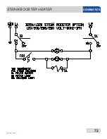
Page 81: ...72 07610 003 78 18 N STEAM BOOSTER HEATER SCHEMATICS ...

Page 82: ...MBER 1 1 Cyclic Temperature Board 06685 002 74 86 2 1 Gauge Cover Red 05700 002 75 62 3 8 Nut Thumb 6 32 Nylon 05310 002 83 12 4 1 Decal Temperature Display 09905 003 78 29 5 2 44 3 66 RTD Temperature Probe not shown 06680 002 16 80 TEMPERATURE BOARD SCHEMATICS ...

Page 83: ... R3 R6 R4 FROM DOOR SWITCH ENSURE RED WHITE TO 12 OF R3 IS CONNECTED HERE RED WHITE RED WHITE RED WHITE RED BLACK RED RED BLACK RED PHOTO EYE CABLE BLUE BROWN WARNING DO NOT CONNECT RED WHITE TO 12 OF R3 HERE ONLY CONNECT RED WHITE TO INPUT 2OF PLC BOARD BROWN RED WHITE RED WHITE BLUE BLUE PURPLE PHOTOCELL TABLE LIMIT SWITCH OPTION SCHEMATICS ...

Page 84: ...75 07610 003 78 18 N 208 230 460 VOLT 60 HZ 3 PHASE 44 ELECTRICALLY HEATED SCHEMATICS ...

Page 85: ...76 07610 003 78 18 N 208 230 VOLT 60 HZ 1 PHASE 44 ELECTRICALLY HEATED SCHEMATICS ...

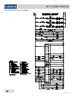
Page 86: ...77 07610 003 78 18 N 208 230 460 VOLT 60 HZ 3 PHASE 44 STEAM HEATED SCHEMATICS ...

Page 87: ...78 07610 003 78 18 N 208 230 VOLT 60 HZ 1 PHASE 44 STEAM HEATED SCHEMATICS ...

Page 88: ...79 07610 003 78 18 N 208 230 460 VOLT 60 HZ 3 PHASE 66 ELECTRICALLY HEATED SCHEMATICS ...

Page 89: ...80 07610 003 78 18 N 208 230 VOLT 60 HZ 1 PHASE 66 ELECTRICALLY HEATED SCHEMATICS ...

Page 90: ...81 07610 003 78 18 N 208 230 460 VOLT 60 HZ 3 PHASE 66 STEAM HEATED SCHEMATICS ...

Page 91: ...82 07610 003 78 18 N 208 230 VOLT 60 HZ 1 PHASE 66 STEAM HEATED SCHEMATICS ...

Page 92: ...83 07610 003 78 18 N BLOWER DRYER 240V SCHEMATICS ...

Page 93: ...84 07610 003 78 18 N BLOWER DRYER 480V SCHEMATICS ...

Page 94: ...85 85 Jackson WWS Inc 6209 N US Hwy 25E Gray KY 40734 USA 1 888 800 5672 www jacksonwws com CREW Manual Rev N 07610 003 78 18 Issued 07 27 10 Revised 8 22 16 ...

Reviews: