background image

1

07610-003-78-18-N

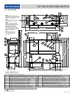
E1

MAIN ELECTRICAL CONNECTION (1.375” DIA HOLE)

E2

BOOSTER HEATER ELECT. CONNECTION (1.375" DIA)

W

MAIN INLET WATER CONNECTION (1/2 NPT-F)

D

DRAIN CONNECTION (1-1/2" NPT-F)

DET

DETERGENT BULKHEAD ACCESS (.875" DIA HOLE)

SAN**

SANITIZER INLET TO RINSE (1/8" NPT-F)

RA

RINSE AID CONNECTION TO RINSE (1/8" NPT-F)

CP

CONDUCTIVITY PROBE ACCESS (.875" DIA HOLE)

S*

STEAM TO WASH TUB HEATING COIL (3/4" NPT-F)

C*

CONDENSATE RETURN (3/4" NPT-F)

VI

VENTILATION DUCT CONN. (LOAD END) 4" x 16" ID

V2

VENTILATION DUCT CONN. (UNLOAD END) 4" x 16" ID

34

 in

67

1 2

 in

71

5

8 in

5112 in MIN

(NOTE 2)

11 in

21 in

23.50

1412 in

618 in

1018 in (NOTE 3)

3

8 in

83

4 in

61

1 8

 in

63

5

8 in

64

1 2

 in

TABLE to TABLE

44 in

633 8 in

93 

in M

A

X

(NO

T

E

 1)

34

 in

20

 in

205 8 in

14

 in

16

1 2

 in

30

1 2

 in

E1

E2

W

V2

V1

S*

C*

D

CP

DET

CP

4 in

73

8 in

RA

SAN

E2

E1

W

23

3

4 in

23

3

4 in

23

3

4 in

33 4 in

1718 in

DET

DET

S*

W

E2

E1

C*

SAN

21

4 in

RA

26

5

8 in

D

77

8 in

19

1 8

 in

1112 in

11

1 2

 in

4418 in

NOTE 2:

VENTILATION DUCT ADAPTERS ARE

ADJUSTABLE FROM 51-1/2" TO 54".

NOTE 1:

THE MAXIMUM DOOR HEIGHT MAY BE

REDUCED BY THE ADDITION OF OPTIONAL

DOOR BRACKETS. MAXIMUM HEIGHTS OF

91", 89" & 87" ARE AVAILABLE.

NOTE 3:

THE DRIVE ASSEMBLY AND GUARD

MAY BE INSTALLED ON EITHER END

OF THE UNIT. INSTALLATION ON THE

UNLOAD END IS STANDARD.  IF

INSTALLED ON THE LOAD END,

PLEASE ENSURE ANY SCRAP SINKS

IN THE TABLING ARE AT AN ADEQUATE

DISTANCE TO PROVIDE FOR CLEARANCE

OF THE DRIVE ASSEMBLY.

15

1

4 in

21

1 2

 in

14

7

8 in

NOTE 4:

ALL VERTICAL DIMENSIONS MAY

VARY DUE TO THE ADJUSTABLE

FEET.

(NOTE 4)

(NOTE 4)

(NOTE 4)

(NOTE 4)

43 8 in

44" LEFT-TO-RIGHT

   *Applies to steam heated units

 ** Chemical sanitizing units only

SPECIFICATIONS

44" MACHINE DIMENSIONS

NOTE 4:

ALL DIMENSIONS FROM THE 

FLOOR CAN BE INCREASED 

1 3/4" USING THE MACHINE'S 

ADJUSTABLE FEET.

Summary of Contents for crew series

Page 1: ...CREW CREW Manual Rev N 07610 003 78 18 Issued 07 27 10 Revised 8 22 16 INSTALLATION OPERATION AND SERVICE MANUAL CREW SERIES CONVEYOR DISHMACHINES...

Page 2: ......

Page 3: ...mproper installation if serial number has been removed or altered or if unit is used for a purpose other than originally intended TRAVEL LIMITATIONS Jackson WWS limits warranty travel time to 2 two ho...

Page 4: ...G 10 27 14 KAP QOF 386 Added new Vent Shield P N 05700 004 18 73 on pg 54 H 03 02 15 KAP N A Updated P N for item 10 on pg 55 J 03 10 15 KAP N A Updated P N for item 4 on pg 71 K 04 17 15 KAP N A Upd...

Page 5: ...ce data plate important note i caustic chemicals ABBREVIATIONS ACRONYMS ANSI American National Standards Institute CFM Cubic Feet per Minute GHT Garden Hose Thread GPM Gallons per Minute GPG Grains pe...

Page 6: ......

Page 7: ...r technical support staff Please have this manual with you when you call so that our staff can refer you if necessary to the proper page Technicalsupportisnotavailable on holidays Contact technical su...

Page 8: ...oubleshooting 24 PARTS Control Box Components 26 Overloads 28 Miscellaneous Electrical Components 29 Wash Heater Heater Shroud Assemblies 30 Pump Suction Assembly 31 Wash Heaters 32 Door Assembly 33 P...

Page 9: ...ly 66 Blower Dryer Option Control Box 67 Blower Dryer Option Blower Assembly 68 SCHEMATICS Booster Heater 3 Phase 69 Booster Heater 1 Phase 12kW 70 Booster Heater 1 Phase 18kW 71 Steam Booster Heater...

Page 10: ...in 7 3 8 in RA SAN E2 E1 W 23 3 4 in 23 3 4 in 23 3 4 in 33 4 in 171 8 in DET DET S W E2 E1 C SAN 2 1 4 in RA 26 5 8 in D 7 7 8 in 19 1 8 in 111 2 in 11 1 2 in 441 8 in NOTE 2 VENTILATION DUCT ADAPTER...

Page 11: ...E UNIT INSTALLATION ON THE UNLOAD END IS STANDARD IF INSTALLED ON THE LOAD END PLEASE ENSURE ANY SCRAP SINKS IN THE TABLING ARE AT AN ADEQUATE DISTANCE TO PROVIDE FOR CLEARANCE OF THE DRIVE ASSEMBLY N...

Page 12: ...in MAX NOTE 1 3 8 in 9 in 2 1 4 in 14 7 8 in 21 1 2 in 26 5 8 in 30 5 8 in TABLE to TABLE 66 in 851 2 in 14 in 16 5 8 in 20 3 8 in 14 7 8 in W2 W3 W1 SAN D1 C S RA D2 E1 E2 W3 W2 E1 E2 W1 RA SAN V1 V2...

Page 13: ...73 1 2 TO 76 NOTE 1 THE MAXIMUM DOOR HEIGHT MAY BE REDUCED BY THE ADDITION OF OPTIONAL DOOR BRACKETS MAXIMUM HEIGHTS OF 91 89 87 ARE AVAILABLE NOTE 4 ALL VERTICAL DIMENSIONS MAY VARY DUE TO THE ADJUST...

Page 14: ...E LOADER DRAIN HOSE SIDE LOADER DRAIN HOSE 23 L R UNHOODED SIDE LOADER 23 R L UNHOODED SIDE LOADER VENTILATION SCOOP VENTILATION SCOOP VENTILATION COWL WITH CUTOUT FOR R L UNITS VENTILATION COWL WITH...

Page 15: ...in 201 4 in W1 S W2 PS PW 33 69 11 3 8 in 22 in 71 2 in E E E E MAIN ELECTRICAL CONNECTION 7 8 DIA HOLE W1 MAIN INLET WATER CONNECTION 3 4 NPT F W2 WATER OUTLET CONNECTION 3 4 NPT F PW WATER PRESSURE...

Page 16: ...Clearance 5 Height 19 75 Width 21 Shipping Weight 750lbs Shipping Size Length 77 Depth 41 Height 89 124 06 48 07 25 50 9 00 ELECTRICAL CONNECTION 25 50 9 00 ELECTRICAL CONNECTION 48 07 102 07 WITH 44...

Page 17: ...5 6 35 6 Pre Wash Tank N A 15 8 N A 15 8 Electrical Loads as applicable Wash Motor HP 3 0 3 0 3 0 3 0 Drive Motor HP 0 25 0 25 0 25 0 25 Pre Wash Motor HP N A 2 0 N A 2 0 Wash Heater kW 15 or 18 18 N...

Page 18: ...ash Temperature 120 120 120 120 Minimum Rinse Temperature 120 120 120 120 Incoming Water Temperature 12 kW Booster 80 80 N A N A 18 kW Booster 50 50 N A N A No Booster 120 120 120 120 Other Water Requ...

Page 19: ...208 230 or 460 Volts Some of the heating elements used in our machines are actually rated for other voltages such as 240 or 480 Volts Always verify the amperage draw of the machine in operation when...

Page 20: ...0 10 0 1 8 86 5 98 3 230 1 60 10 0 1 8 71 9 83 7 240 1 60 10 0 1 8 75 0 86 8 208 3 60 8 6 1 1 50 0 59 7 230 3 60 8 4 1 1 41 5 51 0 240 3 60 8 4 1 1 43 4 52 9 460 3 60 4 2 0 6 20 8 25 6 480 3 60 4 2 0...

Page 21: ...0 0 1 8 21 2 208 3 60 6 8 8 6 1 1 16 5 230 3 60 6 4 8 4 1 1 15 9 460 3 60 3 2 4 2 0 6 8 0 66 Steam Denotes 240 volt heating elements that have been down rated when 230 volts is applied Denotes 480 vol...

Page 22: ...territorial and national codes The installing plumber is responsible for ensuring the incoming water lines are flushed of debris before connecting to the machine Note that chips and materials from cut...

Page 23: ...hine voltage total amperage load and serial number If a data plate has been damaged and cannot be read contact the manufacturer The main power terminal blocks for the dishmachine and for the rinse boo...

Page 24: ...HEMICAL SUPPLY FEEDER SYSTEM For the dishmachine to operate correctly connect it to a third party chemical dispenser that meets the requirements of NSF Standard 29 Contact a chemical supplier about co...

Page 25: ...BOOSTER HEATER ELECTRICAL CONNECTION OPENING 1 375 SHOWN FROM REAR OF LEFT TO RIGHT UNIT RIGHT TO LEFT UNIT IS MIRRORED DETERGENT INJECTION POINT ANOTHER BULKHEAD PLUG IS PROVIDED ON THE LEFT SIDE OF...

Page 26: ...ING REMOVE THIS JUMPER WIRE TO ALLOW FOR TABLE LIMIT SWITCH CONNECTIONS VENT FAN DETERGENT DISPENSER RINSE AID SANITIZER FROM DOOR SWITCH TABLE LIMIT SWITCH CONNECTION CONNECTION POINTS FOR EXTERNAL D...

Page 27: ...S L L XL Load Unload 66 Right to Left XL L L S L S XL Load Unload IMPORTANCE OF PROPER CURTAIN PLACEMENT The curtains inside the dishmachine must be installed properly for the machine to operate corr...

Page 28: ...might be required in some areas Turn off the power supply and place the dishwasher disconnect if applicable in the off position Lockout tag out to prevent the power supply from being turned back on ac...

Page 29: ...ater to inlet side of solenoid valve DRAIN QUENCH SYSTEM IF THERE ARE ANY ISSUES AFTER INSTALLATION PLEASE CONTACT TECHNICAL SERVICE AT 1 888 800 5672 5 Secure all electrical ensure connection is to 1...

Page 30: ...t is placed in the unit will typically reduce the temperature of the wash tank and the first rack might need to run through the unit again This process may be necessary any time the unit has not been...

Page 31: ...t operation of the unit by removing soil and debris that might other wise become trapped in nozzles or deposited onto ware Curtains should be removed and scrubbed with mild detergent and a brush and a...

Page 32: ...r 5 minutes 7 Inspect the inside of the unit to determine if expectations have been met If not try running the delime solution through the unit for more time 8 Once clean drain the machine completely...

Page 33: ...llustration below for the designation of each LED PLC1 is used for the 44 Electric and Steam units An expansion PLC PLC2 is used in conjunction with PLC1 for 66 Electric and Steam units Inputs corresp...

Page 34: ...SED 4 NOT USED 5 NOT USED 6 NOT USED 7 NOT USED 8 NOT USED OUTPUTS 1 PRE WASH TANK FILL SOLENOID 2 PRE WASH MOTOR CONTACTOR 3 NOT USED 4 NOT USED 5 NOT USED 6 NOT USED 7 N A 8 N A INPUTS 1 On Off Swit...

Page 35: ...3 TB1 C2 C1 TB2 PLC2 PLC1 T2 T1 8 9 1 HC1 TB3 TB4 3 2 3 4 6 5 7 1MOL 3MOL 2MOL R1 R2 R3 R4 R5 R6 13 TB5 All operational relays use green LED indicating lights to verify proper operation These relays a...

Page 36: ...L 1 Overload Pre Wash Motor Used on 3 Phase 66 Units See Overload Page TB1 1 Terminal Board Signal 05940 003 77 43 TB2 1 Terminal Board DC 05940 003 77 65 TB3 1 Terminal Board L1 05940 021 94 85 TB4 1...

Page 37: ...fied for 3 phase units only For GE brand MT03 series overloads the process for setting is as follows Determine the Full Load Amps for the drive motor Set the overload at the closest setting without go...

Page 38: ...94 05975 011 49 03 Clamp 1 Conduit 05975 003 77 88 Clamp 3 4 Conduit 05975 003 77 89 Plug 2 5 Hole Louvered 05975 003 77 39 Plug 05975 011 47 81 Plug 05975 002 29 94 Plug 05340 044 46 79 Plug 05975 01...

Page 39: ...1 Gasket Pump Suction 05330 003 75 87 5 1 Gasket Heater 05330 200 02 70 6 1 Heater Box Rails 05700 003 74 72 7 1 Wash Pump Suction Weldment 05700 003 77 63 8 2 Washer S S 05311 174 01 00 9 9 Locknut...

Page 40: ...sket Suction Casting 05330 003 75 89 2 1 Gasket Pump Suction 05330 003 75 87 3 1 Pre Wash Pump Suction Weldment 05700 003 82 27 4 1 Strainer Pre Wash Pump 05700 003 81 28 USED ON ALL PRE WASH TANKS AN...

Page 41: ...79 31 05945 003 75 02 460 3 18 04540 121 79 32 05945 003 75 02 SERVICE NOTES When replacing wash heaters it is highly recommended to change the gasket also Once installed gaskets become compressed an...

Page 42: ...8 PART N DESCRIPTION QTY ITEM 05700 0 F BRACKET DOOR GUIDE 2 1 09330 0 DOOR GUIDE 2 2 05700 0 W DOOR WELDMENT 44 1 3 09330 0 END PIECE DOOR RIGHT SIDE 1 4 09330 0 END PIECE DOOR LEFT SIDE 1 5 05700 0...

Page 43: ...700 003 82 46 12 2 Locknut 6 32 Hex w Nylon Insert 05310 373 03 00 13 1 Cover Door Magnet 05700 004 07 38 DESCRIPTION QTY ITEM F BRACKET DOOR GUIDE 2 1 DOOR GUIDE 2 2 W DOOR WELDMENT 22 PRE WASH 1 3 E...

Page 44: ...NUMBER 1 1 Casting Door Spring Mount 09515 003 73 78 2 1 Spring Door 05315 002 67 29 3 2 Spindle Door Spring 05700 002 67 28 4 1 Pin Door Spring 05700 002 83 55 5 1 Door Spring Bracket Weldment 05700...

Page 45: ...VDC Coil 04810 003 75 16 6 2 Hose 1 2 x 42 S S Braided w PTFE Male Swivel 04720 003 76 09 7 1 Bracket Inlet Plumbing Support 05700 003 74 42 8 1 Bracket Upper Inlet Plumbing Support 05700 003 74 86 Th...

Page 46: ...06 23 3 1 Nipple 1 2 Close Brass 04730 207 15 00 4 1 Gasket Rinse Manifold 05330 003 75 91 5 1 Valve 1 2 NPT Brass 24VDC Coil 04810 003 75 16 6 1 Tube Weldment Tank Fill 05700 003 76 81 7 1 Tank Fill...

Page 47: ...03 76 84 5 2 Elbow 90 Degree 1 2 Brass 04730 206 08 00 6 1 Vacuum Breaker 1 2 Vacuum Breaker Repair Kit 04820 003 06 13 06401 003 06 23 7 2 3 Nipple 1 2 Close Brass 04730 207 15 00 8 1 Tee 1 2 x 1 2 x...

Page 48: ...39 07610 003 78 18 N 1 2 4 5 4 6 7 13 8 9 14 14 10 11 11 10 12 14 13 3 Mechanical Pump Seal 05330 002 34 22 PARTS WASH MANIFOLD ARM ASSEMBLY...

Page 49: ...iser 05700 003 72 37 9 1 Wash Manifold Weldment Upper 05700 003 73 66 10 2 Wash Arm Weldment Right 05700 003 75 80 11 2 Wash Arm Weldment Left 05700 003 75 79 12 12 Cap Threaded 04730 603 12 00 13 3 O...

Page 50: ...6 15 9 8 11 16 13 9 12 8 9 12 8 11 14 16 8 10 10 7 9 8 15 16 5 4 4 3 8 ILLUSTRATES PARTS FOR A LEFT TO RIGHT PRE WASH ILLUSTRATES PARTS FOR A RIGHT TO LEFT PRE WASH Mechanical Pump Seal 05330 002 34 2...

Page 51: ...2 1 2 OD 05330 003 73 72 10 1 Casting Pre Wash Manifold 09515 003 77 22 11 1 Tube Manifold Riser 05700 003 81 53 12 1 Wash Manifold Weldment Upper 05700 003 81 76 13 1 Wash Arm Weldment Left 05700 003...

Page 52: ...43 07610 003 78 18 N RINSE INJECTOR CONNECTIONS P PRESSURE SWITCH S SANITIZER R RINSE AID NOTE 1 NOTE 2 5 14 16 3 4 17 22 22 21 20 23 18 8 1 9 8 15 7 1 2 1 19 16 6 12 10 10 11 5 PARTS RINSE ASSEMBLY...

Page 53: ...6 10 2 Plug 1 8 NPT Brass 04730 209 07 37 11 1 Gasket Rinse Manifold 05330 003 75 91 12 1 Fitting Imperial Brass 05310 924 02 05 13 1 Plug 1 4 04730 209 01 00 14 3 O Ring Silicon 103 Dia 11 16 x 7 8 O...

Page 54: ...6 3 4 3 5 TYPICAL PAWL DOG WITH HARDWARE ITEM QTY DESCRIPTION PART NUMBER 1 1 Pawl Bar Weldment 44 Units 05700 031 72 77 2 1 Pawl Bar Weldment 66 Units 05700 003 89 34 3 24 44 36 66 Spacer Pawl Bar D...

Page 55: ...20 x 1 3 4 Hex Head 05305 274 10 00 3 8 Locknut 1 4 20 Hex w Nylon Insert 05310 374 01 00 4 6 Washer S S 05311 174 01 00 5 2 Roller Bracket Rod 05700 011 68 16 6 2 Shaft Roller 3 8 x 1 13 05700 011 68...

Page 56: ...NUMBER 1 1 Top Guide Block 05700 011 69 49 2 1 Bottom Guide Block 05700 011 69 50 3 1 Pawl Bar Gutter Weldment 05700 021 66 86 4 1 Drive Gutter Gasket not shown 05330 011 68 55 1 Gutter Weldment Repl...

Page 57: ...4 82 3 2 Screw 1 4 20 x 7 8 S S 05305 274 05 00 4 2 Locknut 1 4 20 Low Profile w Nylon Insert 05310 374 02 00 5 1 Locknut 1 4 20 Hex w Nylon Insert 05310 374 01 00 6 1 Screw 1 4 20 x 2 3 4 Hex Head 05...

Page 58: ...700 003 81 91 05700 003 81 96 2 1 Stud 1 4 20 x 8 50 Long S S Double Ended Thread 05306 003 76 31 3 2 Locknut 1 4 20 Hex w Nylon Insert 05310 374 01 00 4 2 Locknut 1 4 20 Low Profile w Nylon Insert 05...

Page 59: ...in Handle Bracket 05700 003 83 67 4 2 Drain Standpipe 05700 003 82 76 5 1 O Ring 05330 400 05 00 6 2 Locknut 1 4 20 Hex w Nylon Insert 05310 374 01 00 THIS CONFIGURATION IS USED FOR THE 66 UNIT WASH T...

Page 60: ...WN BY DATE 05700 004 03 88 F COVER 44 TUB SIDE LEFT B GAMBREL 4 16 2013 A C WO 15 06 UP 90 UP 90 DOWN 90 UP 90 UP 90 UP 90 UP 90 1 452 0 577 1 367 1 367 0 452 1 356 PAPER OTHER SIDE GRAIN 0 567 16 897...

Page 61: ...5700 003 77 87 Limit Switch Bracket 05700 021 71 18 Upper Drive Support Bracket 05700 003 77 18 Panel Bracket Left 05700 003 78 13 Lower Drive Support Bracket 05700 003 77 19 Panel Bracket Right 05700...

Page 62: ...L R 05700 003 81 89 66 R L Rear Rack Rail 05700 003 77 54 44 Units 05700 003 80 57 66 Units Curtain Bracket End 05700 003 77 60 Curtain Bracket Middle 05700 003 77 61 Strainer Wash Tank 05700 003 74 3...

Page 63: ...cent Panel option Ventilation Cowl Right Side for Door Accent Panel option 05700 003 77 50 05700 003 75 77 05700 003 75 78 2 2 Ventilation Scoop 05700 003 75 74 3 2 Ventilation Duct Adapter 05700 003...

Page 64: ...pring 05311 274 01 00 10 3 Bolt 1 4 20 x 1 2 Long 05305 274 02 00 To attach the curtain and rod to the Ventilation Cowl ensure that the curtain is oriented as depicted and follow the steps below 1 Ins...

Page 65: ...56 07610 003 78 18 N 24 6 3 17 23 15 13 9 26 14 22 20 21 12 10 19 29 29 28 16 13 14 16 13 8 25 11 4 5 20 11 27 21 13 16 2 11 1 14 15 13 17 13 7 30 DRIVE ASSEMBLY PARTS...

Page 66: ...t S S 05311 176 01 00 15 12 Nut Hex 3 8 16 S S 05310 276 01 00 16 4 Bolt 3 8 16 x 1 3 4 Long 05306 011 36 94 17 4 3 8 16 x 1 3 4 Long 05306 011 71 60 18 2 Washer S S 1 4 20 not shown 05311 174 01 00 1...

Page 67: ...s a 23 Right to Left Unhooded Side Loader Differences in parts for the 23 Left to Right and both directions of the 30 Side Loaders are reflected in the parts list NOTE NOTE NOTE Order lengths of Hose...

Page 68: ...16 B 7 16 DETAIL B 21 24 24 20 14 16 14 16 23 16 22 This illustration depicts a 23 Right to Left Unhooded Side Loader Differences in parts for the 23 Left to Right and both directions of the 30 Side L...

Page 69: ...39 14 16 Washer 1 4 S S 05311 174 01 00 15 4 Bolt 1 4 20 x 1 2 Long 05305 274 02 00 16 39 Locknut 1 4 20 Hex w Nylon Insert 05310 374 01 00 17 2 Roller 05700 011 68 16 18 2 Screw 1 4 20 x 1 3 4 Long...

Page 70: ...der 05700 001 99 16 3 3 Pawl Dog w Wing 05700 021 86 79 4 3 Locknut 3 8 16 w Nylon Insert 05310 011 72 55 5 3 Bolt 3 8 16 x 1 3 4 Long Hex Head 05306 011 36 94 6 6 Spacer Pawl Bar Dog 05700 011 71 45...

Page 71: ...nt 05700 003 83 79 8 4 Gasket Steam Coil 05700 001 17 86 9 2 Washer Steam Coil Adapter 05700 001 17 87 10 2 Nut Steam Coil Adapter 05310 011 17 85 11 2 Reducer 3 4 x 1 2 Black Iron 04730 911 02 34 12...

Page 72: ...DESCRIPTION PART NUMBER 1 1 Booster Heater See Chart Below 2 2 Hose 1 2 x 42 S S Braided 04720 003 76 09 3 2 Elbow 3 4 90 Deg Brass 04730 206 13 00 4 2 Bushing 3 4 x 1 2 Hex Brass 04730 002 56 27 5 2...

Page 73: ...4 13 12 11 10 9 4 5 4 4 7 8 2 24 17 1 2 3 6 ITEM QTY DESCRIPTION PART NUMBER 1 1 Steam Booster Heater ST T120 04420 002 43 94 2 2 U Bolt 1 2 13 Thread Zinc Coated 05306 002 89 27 3 1 Steam Trap 3 4 06...

Page 74: ...Ball Test Cock 1 4 Bronze 04810 011 72 67 22 2 Pressure Gauge 1 4 0 100 PSI 06685 111 88 34 23 23A 23B 23C 23D 23F 1 Control J120 Assembly Major Components Listed Below Thermostat Corkscrew Switch Lig...

Page 75: ...003 75 73 3 1 DOOR ASSEMBLY BLOWER 05700 004 00 32 4 1 PANEL WELDMENT EXHAUST TOP 05700 004 00 61 5 1 PANEL BLOWER TUB SIDE RIGHT 05700 004 03 93 6 1 Panel Front Dress 05700 004 01 99 1 Panel Blower H...

Page 76: ...5 08 5 1 Relay Socket 16A 300V 05945 003 79 58 6 1 Contactor 24VDC 460V 5HP 05945 003 75 22 7 2 Heater Contactor 600V 25A 24VDC Coil 05945 004 10 63 8 1 Overload Blower Motor 460V Overload Blower Moto...

Page 77: ...ower Air 04540 002 74 29 3 1 Blower Heater Box Weldment 05700 004 00 72 4 8 Bolt Hex Head 1 4 20 x 3 4 05305 274 04 00 5 8 Washer S S 1 4 20 I D 05311 174 01 00 6 8 Locknut 1 4 20 Hex w Nylon Insert 0...

Page 78: ...WING BOOSTER HEATER OPTIONS 208V 60Hz 3 Phase 12 kW 40 Rise 230V 60Hz 3 Phase 12 kW 40 Rise 460V 60Hz 3 Phase 12 kW 40 Rise 208V 60Hz 3 Phase 18 kW 70 Rise 230V 60Hz 3 Phase 18 kW 70 Rise 460V 60Hz 3...

Page 79: ...70 07610 003 78 18 N USE THIS SCHEMATIC FOR THE FOLLOWING BOOSTER HEATER OPTIONS 208V 60Hz 1 Phase 12 kW 40 Rise 230V 60Hz 1 Phase 12 kW 40 Rise BOOSTER HEATER 1 PHASE 12kW SCHEMATICS...

Page 80: ...71 07610 003 78 18 N USE THIS SCHEMATIC FOR THE FOLLOWING BOOSTER HEATER OPTIONS 208V 60Hz 1 Phase 18 kW 70 Rise 230V 60Hz 1 Phase 18 kW 70 Rise BOOSTER HEATER 1 PHASE 18kW SCHEMATICS...

Page 81: ...72 07610 003 78 18 N STEAM BOOSTER HEATER SCHEMATICS...

Page 82: ...BER 1 1 Cyclic Temperature Board 06685 002 74 86 2 1 Gauge Cover Red 05700 002 75 62 3 8 Nut Thumb 6 32 Nylon 05310 002 83 12 4 1 Decal Temperature Display 09905 003 78 29 5 2 44 3 66 RTD Temperature...

Page 83: ...R3 R6 R4 FROM DOOR SWITCH ENSURE RED WHITE TO 12 OF R3 IS CONNECTED HERE RED WHITE RED WHITE RED WHITE RED BLACK RED RED BLACK RED PHOTO EYE CABLE BLUE BROWN WARNING DO NOT CONNECT RED WHITE TO 12 OF...

Page 84: ...75 07610 003 78 18 N 208 230 460 VOLT 60 HZ 3 PHASE 44 ELECTRICALLY HEATED SCHEMATICS...

Page 85: ...76 07610 003 78 18 N 208 230 VOLT 60 HZ 1 PHASE 44 ELECTRICALLY HEATED SCHEMATICS...

Page 86: ...77 07610 003 78 18 N 208 230 460 VOLT 60 HZ 3 PHASE 44 STEAM HEATED SCHEMATICS...

Page 87: ...78 07610 003 78 18 N 208 230 VOLT 60 HZ 1 PHASE 44 STEAM HEATED SCHEMATICS...

Page 88: ...79 07610 003 78 18 N 208 230 460 VOLT 60 HZ 3 PHASE 66 ELECTRICALLY HEATED SCHEMATICS...

Page 89: ...80 07610 003 78 18 N 208 230 VOLT 60 HZ 1 PHASE 66 ELECTRICALLY HEATED SCHEMATICS...

Page 90: ...81 07610 003 78 18 N 208 230 460 VOLT 60 HZ 3 PHASE 66 STEAM HEATED SCHEMATICS...

Page 91: ...82 07610 003 78 18 N 208 230 VOLT 60 HZ 1 PHASE 66 STEAM HEATED SCHEMATICS...

Page 92: ...83 07610 003 78 18 N BLOWER DRYER 240V SCHEMATICS...

Page 93: ...84 07610 003 78 18 N BLOWER DRYER 480V SCHEMATICS...

Page 94: ...85 85 Jackson WWS Inc 6209 N US Hwy 25E Gray KY 40734 USA 1 888 800 5672 www jacksonwws com CREW Manual Rev N 07610 003 78 18 Issued 07 27 10 Revised 8 22 16...

Reviews: