13
07610-003-78-18-N
INSTALLATION
INSTRUCTIONS
Before installing the unit, check the packaging and the machine for damage. Damaged
packaging might be an indication there is possible damage to the product. If there is
any type of damage to both the packaging and the unit, DO NOT THROW AWAY THE
PACKAGING. The dishmachine has been previously inspected at the factory and is
expected to arrive in new, undamaged condition. However, rough handling by carriers
or others might result in damage to the unit while it is in transit. If this occurs, DO NOT
RETURN THE UNIT TO THE MANUFACTURER. Instead, contact the carrier and ask them
to send a representative to the site to inspect the damage and request that an inspection
report be completed. Contact the carrier and dealer that sold you the unit within 48 hours
of receiving the machine in order to report possible freight damage.
The machine should be unboxed and removed from the pallet before installing. Remove
the wooden lift beams and their associated brackets after the unit has been positioned.
Open the front door and remove all materials from inside. Once unpacked, verify there are
no missing parts. If a part is missing, contact the manufacturer immediately.
The dishmachine is designed to operate while level. This is important to prevent any damage
to the machine during operation and to ensure the best possible results. The unit comes
equipped with adjustable bullet feet, which can be turned using a pair of pliers. Verify the
unit is level from front-to-back and side-to-side before making any electrical or plumbing
connections.
All plumbing connections must be made to adhere to local, state, territorial, and national
codes. The installing plumber is responsible for ensuring the incoming water lines are
flushed of debris before connecting to the machine. Note that chips and materials from
cutting processes can become lodged in the solenoid valves and prevent them from
opening or closing. Any valves that are found to be fouled or defective because of foreign
matter left in the water line and any subsequent water damage are not the responsibility of
the manufacturer.
Water hardness should be a maximum of 6 GPG. Hard w
ater should be treated before
being used by the machine. Iron in the water line can cause staining. A filter designed
to remove iron from the water supply is highly recommended for supplies in excess of
0.1 ppm.
This dishmachine comes with a pressure regulator. The unit utilizes
a flow pressure of 15
PSI for the incoming water line. Do not confuse static pressure with flow pressure. Static
pressure occurs when there is no flow and the valves are closed. Flow pressure occurs
when water is running into the machine. The pressure regulator should be adjusted to the
proper flow pressure indicated on the data plate.
The water supply line must be 1/2" NPT minimum and must be able to provide water at t
he
minimum temperature indicated on the machine data plate.
A shut-off valve should be installed to allow isolating the dishmachine from the water
system in the event service is required. It is also suggested that a shock absorber (
not
supplied
with dishmachine) be installed on the incoming water line. This prevents water
hammer (hydraulic shock)—induced by the solenoid valve as it operates—from causing
damage to the equipment.
VISUAL
INSPECTION
LEVEL THE
DISHMACHINE
UNPACKING THE
MACHINE
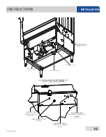
PLUMBING THE
DISHMACHINE
Do not throw away the
container if damage is
evident!
i
The plumber MUST flush
the incoming water line!
Summary of Contents for crew series
Page 2: ......
Page 6: ......
Page 81: ...72 07610 003 78 18 N STEAM BOOSTER HEATER SCHEMATICS...
Page 84: ...75 07610 003 78 18 N 208 230 460 VOLT 60 HZ 3 PHASE 44 ELECTRICALLY HEATED SCHEMATICS...
Page 85: ...76 07610 003 78 18 N 208 230 VOLT 60 HZ 1 PHASE 44 ELECTRICALLY HEATED SCHEMATICS...
Page 86: ...77 07610 003 78 18 N 208 230 460 VOLT 60 HZ 3 PHASE 44 STEAM HEATED SCHEMATICS...
Page 87: ...78 07610 003 78 18 N 208 230 VOLT 60 HZ 1 PHASE 44 STEAM HEATED SCHEMATICS...
Page 88: ...79 07610 003 78 18 N 208 230 460 VOLT 60 HZ 3 PHASE 66 ELECTRICALLY HEATED SCHEMATICS...
Page 89: ...80 07610 003 78 18 N 208 230 VOLT 60 HZ 1 PHASE 66 ELECTRICALLY HEATED SCHEMATICS...
Page 90: ...81 07610 003 78 18 N 208 230 460 VOLT 60 HZ 3 PHASE 66 STEAM HEATED SCHEMATICS...
Page 91: ...82 07610 003 78 18 N 208 230 VOLT 60 HZ 1 PHASE 66 STEAM HEATED SCHEMATICS...
Page 92: ...83 07610 003 78 18 N BLOWER DRYER 240V SCHEMATICS...
Page 93: ...84 07610 003 78 18 N BLOWER DRYER 480V SCHEMATICS...

