14
07610-003-78-18-N
INSTRUCTIONS
INSTALLATION
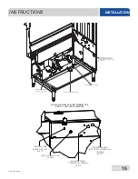
The drain for the unit is a gravity discharge drain. All piping to the machine drain must be
a minimum 1-1/2” NPT AND MUST NOT BE REDUCED. There must also be an air gap
between the machine drain line and the floor sink or drain. If a grease trap is required by
code, it should have a flow capacity of 5 GPM. 44" units have one drain connection point
and 66" units have two.
Some machines covered in this manual are designed to use low-pressure steam as a
source of heat for the wash tank. Those machines come with lines by which an outside
source of steam (e.g. steam booster) is connected. Connect all steam lines from the
booster to the machine in accordance with the booster manufacturer’s instructions. Ensure
that all applicable codes and regulations are adhered to. See the machine data plate for
information related to steam flow requirements.
All electrical connections are to be made in accordance with applicable portions of local,
state, territorial, and national codes.
This manual provides reference information regarding electrical requirements and loads,
but that information may change without notice. Always refer to the machine data plate for
voltage requirements, machine voltage, total amperage load, and serial number. If a data
plate has been damaged and cannot be read, contact the manufacturer.
The main power terminal blocks (for the dishmachine and for the rinse booster heater, if
applicable) are located at the top of the machine. Remove the top cover to access these
connections. Route incoming power lines within conduit that will connect via fittings to the
pre-punched holes in the back of the control box. Install power and ground wires to lugs as
indicated by the appropriate decals in the control box. Use copper conductors only. Use of
an anti-oxidation agent is permissible on the power connections. Tighten all connections.
Verify the incoming voltage matches the voltage indicate
d on the decal next to the
incoming power pre-punched hole.
NOTE:
The dishmachine has a separate power connection from the rinse booster heater
and the circuit protection requirements are different for each. Refer to the machine data
plate for information on minimum circuit protection.
CAUTION:
Improperly connecting external devices can cause damage to the machine
and/or electrical infrastructure!
SEE PAGE 17 FOR A GUIDE ON WIRING EXTERNAL DEVICES (EXHAUST FAN,
CHEMICAL DISPENSERS, ETC.)
CONNECTING
THE DRAIN LINE
STEAM LINE
CONNECTIONS
ELECTRICAL
POWER
CONNECTIONS
Disconnect electrical
power at the breaker or
disconnect switch and
tag-out in accordance
with procedures and
codes.
!
CAUTION
i
NOTICE
Summary of Contents for crew series
Page 2: ......
Page 6: ......
Page 81: ...72 07610 003 78 18 N STEAM BOOSTER HEATER SCHEMATICS...
Page 84: ...75 07610 003 78 18 N 208 230 460 VOLT 60 HZ 3 PHASE 44 ELECTRICALLY HEATED SCHEMATICS...
Page 85: ...76 07610 003 78 18 N 208 230 VOLT 60 HZ 1 PHASE 44 ELECTRICALLY HEATED SCHEMATICS...
Page 86: ...77 07610 003 78 18 N 208 230 460 VOLT 60 HZ 3 PHASE 44 STEAM HEATED SCHEMATICS...
Page 87: ...78 07610 003 78 18 N 208 230 VOLT 60 HZ 1 PHASE 44 STEAM HEATED SCHEMATICS...
Page 88: ...79 07610 003 78 18 N 208 230 460 VOLT 60 HZ 3 PHASE 66 ELECTRICALLY HEATED SCHEMATICS...
Page 89: ...80 07610 003 78 18 N 208 230 VOLT 60 HZ 1 PHASE 66 ELECTRICALLY HEATED SCHEMATICS...
Page 90: ...81 07610 003 78 18 N 208 230 460 VOLT 60 HZ 3 PHASE 66 STEAM HEATED SCHEMATICS...
Page 91: ...82 07610 003 78 18 N 208 230 VOLT 60 HZ 1 PHASE 66 STEAM HEATED SCHEMATICS...
Page 92: ...83 07610 003 78 18 N BLOWER DRYER 240V SCHEMATICS...
Page 93: ...84 07610 003 78 18 N BLOWER DRYER 480V SCHEMATICS...

