background image

38

07610-003-62-15-Q

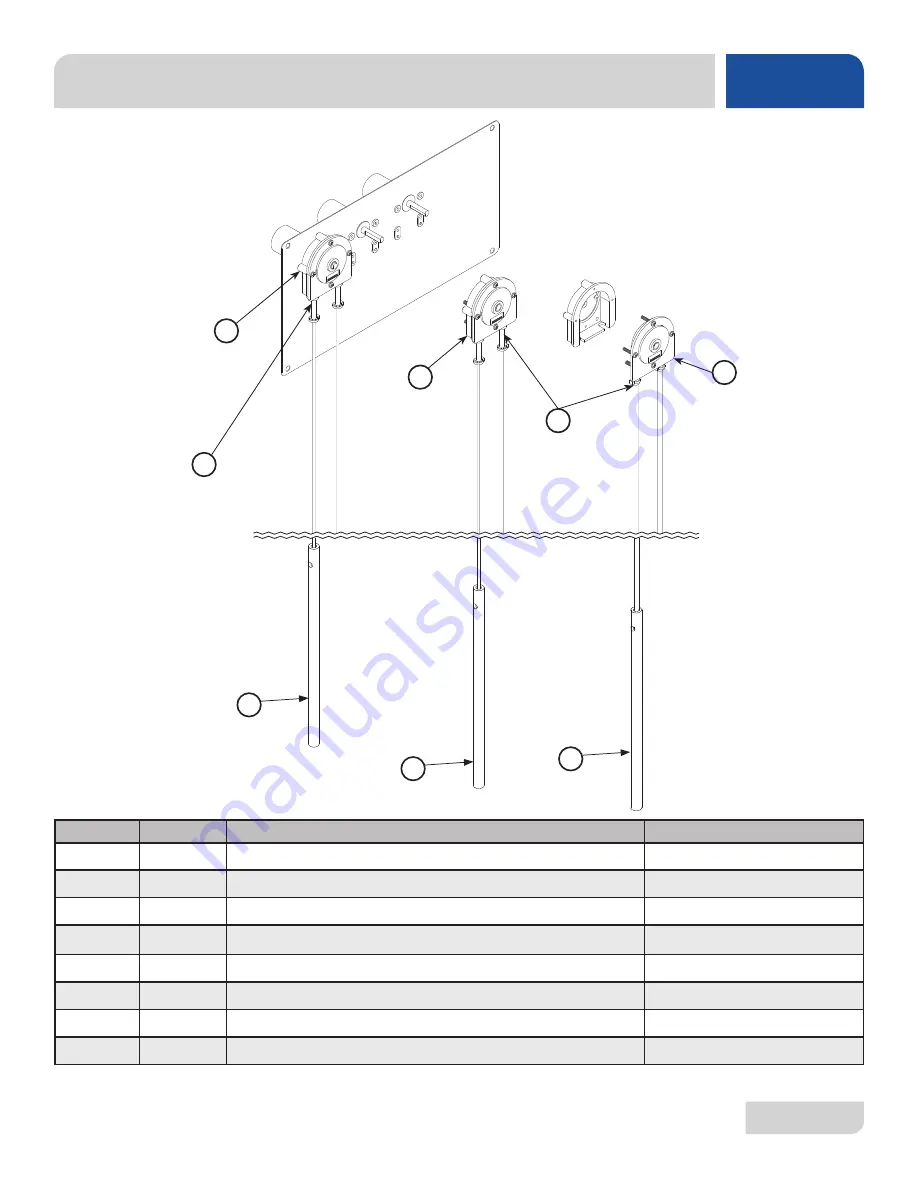
CHEMICAL FEEDER PUMP ASSEMBLY

PARTS

4

ITEM

QTY

DESCRIPTION

PART NUMBER

1

1

14 RPM Peri-Pump

05700-003-87-08

2

1

Cover and Peri-Pump Assembly

05700-003-55-29

3

1

Cover only

05700-003-55-34

4

1

Sanitizer Tube Replacement Kit

06401-003-61-21

5

1

Rinse Aid Tube Replacement Kit

06401-003-61-22

6

1

Detergent Tube Replacement Kit

06401-003-61-23

7

2

Rinse Aid & Sanitizer Squeeze Tubes

05700-011-65-21

8

1

Detergent Squeeze Tube

05700-003-22-89 

1

3

7

8

2

5

6

Summary of Contents for DELTA 115

Page 1: ...DELTA 1200 115 INSTALLATION OPERATION AND SERVICE MANUAL Delta 1200 115 Manual Rev Q 07610 003 62 15 Issued 10 27 08 Revised 9 19 16 DELTA SERIES GLASSWASHER DISHMACHINES ...

Page 2: ......

Page 3: ...improper installation if serial number has been removed or altered or if unit is used for a purpose other than originally intended TRAVEL LIMITATIONS Jackson WWS limits warranty travel time to 2 two hours and mileage to 100 one hundred miles Jackson WWS will not pay for travel time and mileage that exceeds this or any additonal fees such as those for air or boat travel without prior authorization ...

Page 4: ...acement of item s 36 and 31 I 09 15 14 KAP N A Updated Jackson Logo J 01 30 15 KAP QOF 386 Updated part list on pg 42 K 08 07 15 KAP N A Updated detergent squeeze tube P N Updated and labeled rinse aid and sanitizer squeeze tubes pgs 33 34 L 10 08 15 KAP N A Updated item 9 P N to 05700 003 60 38 on pg 32 M 11 19 15 JH ECN 8336 Added Delta 115 and associated schematics etc N 01 19 16 JH QOF 386 Upd...

Page 5: ...o that our staff can refer you if necessary to the proper page Technical support is not available on holidays Contact technical support toll free at 1 888 800 5672 Technical support is available for service personnel only DELTA 1200 208 V glasswasher dishmacine chemical sanitizing carousel type electric tank heat with detergent rinse aid and sanitizer chemical feeder pumps DELTA 115 115 V glasswas...

Page 6: ......

Page 7: ...ce 16 TROUBLE SHOOTING Common Problems 17 SERVICE PROCEDURES Chemical Feeder Pump Motor Replacement 21 Wash Tank Heater Replacement 24 Thermostat Replacement 29 Wash Motor Replacement 32 PARTS Control Box Assembly Delta 115 35 Control Box Assembly Delta 1200 36 Outer Shell Assembly 37 Chemical Feeder Pump Assembly 38 Rinse Assembly 39 Wash System 41 Conveyor Drive System 43 Door Assembly 45 SCHEMA...

Page 8: ...plate important note i caustic chemicals ABBREVIATIONS ACRONYMS ANSI American National Standards Institute GHT Garden Hose Thread GPH Gallons per Hour GPM Gallons per Minute GPG Grains per Gallon HP Horse Power Hz Hertz ID Inside Diameter kW Kilowatts NFPA National Fire Protection Association NPT National Pipe Thread PPM Parts per Million PSI Pounds per Square Inch V Volts ground wire ...

Page 9: ...ONT VIEW OVER VIEW LEGEND Scale 0 09 1 A Designates the machine s rightmost side from the front B Designates the machine s base 1 1 2 38 mm Drainline Connection All dimensions are for reference only and are subject to change without notice MACHINE DIMENSIONS SPECIFICATIONS LEGEND A Designates the machine s rightmost side from the front B Designates the machine s base All dimensions from the floor ...

Page 10: ...Flow Pressure PSI 8 12 8 12 Hot Water Flow Pressure PSI 20 5 20 5 Gallons per Hour 10 0 10 0 Water Line Size NPT 1 2 1 2 Drain Line Size NPT 1 1 2 1 1 2 Minimum Chlorine Required PPM 50 50 Electrical Loads as applicable Wash Motor HP 0 1 0 1 Wash Heater kW 2 7 208 V 3 3 230 V 1 3 NOTE Always refer to the machine data plate for specific electrical and water requirements The material provided on thi...

Page 11: ...assumed input voltage The manufacturer assumes incoming voltages will be either 208 or 230 Volts Some heating elements used in the machines could be rated for other voltages so always verify the amperage draw of the machine in operation when sizing circuit protection If the dishmachine is equipped with an optional rinse heater note the rinse heater might have its own electrical connection and requ...

Page 12: ... which can be turned using a pair of pliers Verify the unit is level from front to back and side to side before making any electrical or plumbing connections All plumbing connections must be made to adhere to local state territorial and national codes The installing plumber is responsible for ensuring the incoming water lines are flushed of debris before connecting to the machine Note that chips a...

Page 13: ...nstalled on the incoming water line This prevents water hammer hydraulic shock induced by the solenoid valve as it operates from causing damage to the equipment The Delta glasswashers have a gravity drain 2 NPT connection All piping from the machine to the drain must be a minimum 2 NPT and must not be reduced There must also be an air gap between the machine drain line and the floor sink or drain ...

Page 14: ...n the OFF position and apply power to dishmachine Check the incoming power at the terminal block and ensure it corresponds with the voltage listed on the data plate If not contact a qualified service agency to examine the problem Do not run dishmachine if voltage is too high or too low Shut off the service breaker and advise all proper personnel of the location of the breaker and any problems Repl...

Page 15: ...hen the machine is first installed or if the chemical lines have been removed and air is allowed to enter CAUTION Watermustbeinthesumpandwashtankbeforechemicals are dispensed This equipment is not recommended for use with deionized water or other aggressive fluids 1 Verify that the proper chemical tube stiffener inlet is in the proper container 2 Use the push buttons on the right side of control b...

Page 16: ...is clean and in place 2 Rinse strainer is clean and in place 3 The drain stopper is installed 4 Chemical levels in chemical containers are correct 1 Place the Power switch in the FILL position 2 The unit will automatically begin to fill 3 Verify temperatures before operating the unit PREPARATION FILLING THE WASH TUB ...

Page 17: ...N position the carousel will begin to rotate 2 Place glasses upside down on the carousel 3 When the glasses have completed the cycle the paddle switch will activate turning off the water and carousel 4 Remove clean glasses which are against the paddle switch 5 The carousel will begin to rotate again Based on use the strainers might become clogged with soil and debris as the workday progresses Oper...

Page 18: ...CTIONS OPERATION 3 Remove and clean the wash strainer 4 Remove and clean the drain stopper 5 Remove the curtain clean with a mild soap and rinse 6 Remove and clean the drain boards 7 Remove and clean the rack cylinder SHUTDOWN AND CLEANING ...

Page 19: ... of machine with one hand 9 Remove carousel with other hand and clean the carousel 10 Push the wash and rinse arms away from their manifolds and remove Remove end caps clean with a brush and flush with fresh water 11 Remove and clean the separator and upper rinse strainer 12 Remove and clean the rinse strainer ...

Page 20: ...CTIONS OPERATION AFTER CLEANING 1 Spray or wipe out interior of machine 2 Replace the rinse strainer 3 Replace the separator and upper rinse strainer 4 Replace wash rinse arms and verify end caps have been tightened 5 Replace the carousel ...

Page 21: ...CTIONS OPERATION 6 Replace the rack cylinder 7 Replace the drain boards 8 Replace the curtain 9 Replace the drain stopper 10 Replace the wash strainer 11 Use stainless steel polish to clean and protect outside of dishmachine AFTER CLEANING ...

Page 22: ...t might be necessary to install a water treatment unit for the water going to the dishmachine only Discuss this option with a qualified water treatment specialist 4 Dishmachine operators should be properly trained on how much detergent is to be used per cycle Meet with a water treatment specialist and detergent vendor to discuss a complete training program for operators 5 This dishmachine requires...

Page 23: ...iners are clean and securely in place before operating the machine When cleaning out strainers do NOT beat them on waste cans Wipe out strainers with a rag and rinse under a faucet if necessary Use a toothpick to dislodge any stubborn debris 3 Ensure that all wash and rinse arms are secure in the machine before operating 4 Ensure that the drain stopper is installed correctly seated vertically in t...

Page 24: ... properly to machine and that it is turned on 2 Replace diaphragm and clean out valve Measure continuity on coil if there is none replace the coil 3 Ohm out the switch to ensure that upper and lower floats are working If not check float wiring to see if it is correct if so replace float Machine fills continuously even with no power to the dishmachine 1 Solenoid valve jammed stuck in the open posit...

Page 25: ...ce Low water pressure 1 Drain clogged 2 Defective drain valve 1 Remove obstruction 2 Replace No indication of pressure 1 Water level is too low 2 Wash arms clogged 3 Obstruction in pump housing 4 O ring at wash tank drain cut or missing 1 Ensure that incoming water line pressure meets the requirements on dishmachine data plate 2 Remove wash arms and clean 3 Disassemble and clear 4 Replace Low wash...

Page 26: ... 1 If there is not line voltage between BLACK YELLOW and ORANGE BLUE wires to prime switch replace 2 Check operation of board If not working properly replace Sanitizer pump does not run during cycle but runs when primed even when turntable is off 1 Loose or broken wire 2 Faulty speed control board 3 Faulty prime switch 1 Replace or tighten 2 Check operation of board If not working properly replace...

Page 27: ...ace 2 Replace hose or squeeze tube as needed No indication of pressure 3 Machine not in fill mode Normal operation 1 Ensure that incoming water line pressure meets the requirements on dishmachine data plate 2 Remove wash arms and clean 3 Disassemble and clear 4 Replace Wash heater does not work NOTE push wash heater contactor bar down and take amperage reading Amps should be correct as stated on t...

Page 28: ... Strippers Crimping Tool IMPORTANT NOTES Read these instructions thoroughly before attempting this maintenance task Become familiar with the parts and what actions need to be taken This will save time in the long run These instructions show steps on only one of the three motors However the steps are the same for each one STEPS 1 Remove the front door 2 Remove the electrical box cover with the phil...

Page 29: ...e motor wire from the prime switch being careful not to damage the prime switch in the process If the prime switch is damaged it will need to be replaced 6 Turn the cover over and using the phillips screwdriver remove the cover to the pump requiring a motor change 7 With the cover removed gently pull out the rubber tube from inside the pump 8 Remove the roller by pulling it off of the shaft 9 Usin...

Page 30: ...r wire and the wire for the priming switch 16 Put the cover back on the control box and secure with the two screws previously removed 17 Ensuring that all non essential personnel are clear of the area and restore power to the unit Turn the unit on Using the priming switch verify that the feeder pump operates and pumps fluid 18 Replace the front door Work performed on dishmachines by unauthorized o...

Page 31: ...S REQUIRED 3 8 Nutdriver Ratchet 1 2 Socket Wrench 3 8 Socket Wrench Torque Wrench Amp Meter Phillips Screwdriver IMPORTANT NOTES Read these instructions thoroughly before attempting this maintenance task Become familiar with the parts and what actions need to be taken This will save time in the long run These instructions show steps on only one of the three motors However the steps are the same f...

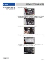
Page 32: ... and let the thermostat hang down out of the way 5 Remove the thermostat bracket with the 3 8 nutdriver 6 Remove the upper wash strainer Set both strainers to the side where they will not be damaged or present a trip hazard 7 Using the 3 8 nutdriver remove the nuts securing the heater wires to the heater Then carefully pull the wires out of the way WASH TANK HEATER REPLACEMENT ...

Page 33: ...is pushed away from the tank wall pull it out with your hands 11 Remove the old heater gasket and throw away 12 Apply the new heater gasket 13 Take the new heater and slide it through the hole in the wash tank and line it up so the wash tank studs fit in the holes on the heater flange Step 10 in reverse 14 Place the mounting nuts and lockwashers on the studs and secure them with a 1 2 socket or wr...

Page 34: ...re clear of the area place the drain stopper back in the wash tank and restore power and water to the unit Turn the unit on and allow it to fill normally 21 Verify that there are no leaks around the heater If there are attempt to tighten it down with power secured to the unit at the service breaker to prevent injury as the tank will change shape slightly as it heats up 22 Use the amp meter to take...

Page 35: ...Secure power to the unit at the service breaker and then verify the torque of all fasteners covered in this instruction Work performed on dishmachines by unauthorized or unqualified personnel may void the warranty Before beginning this or any other maintenance on a unit under warranty you should contact a manufacturer certified technician or the manufacturer s Technical Service WASH TANK HEATER RE...

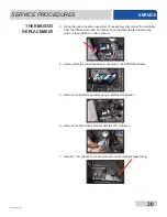
Page 36: ...ed TOOLS REQUIRED 3 8 Nutdriver 7 16 Nutdriver 7 16 Wrench Needle nose Pliers Phillips Screwdriver IMPORTANT NOTES Read these instructions thoroughly before attempting this maintenance task Become familiar with the parts and what actions need to be taken This will save time in the long run These instructions show steps on only one of the three motors However the steps are the same for each one STE...

Page 37: ...careful not to damage the terminals or the wires or they will have to be replaced 4 Unplug all of the terminals wires connected to the ELAN thermostat 5 Remove the ELAN thermostat using a phillips screwdriver 6 Remove the thermostat bracket with the 3 8 nutdriver 7 Use the 7 16 wrench to loosen and remove the imperial brass fitting THERMOSTAT REPLACEMENT ...

Page 38: ...he drain stopper back in the wash tank Restore power and water to the unit Then allow the unit to operate normally 14 Verify that the thermostat operates the heater contactor Once you have determined the heater contactor is working adjust the wash tank thermostat to ensure that the temperature is maintained in accordance with the specifications on the machine data plate 15 Replace the heater cover...

Page 39: ...ver 7 16 Wrench Needle nose Pliers Phillips Screwdriver IMPORTANT NOTES Read these instructions thoroughly before attempting this maintenance task Become familiar with the parts and what actions need to be taken This will save time in the long run These instructions show steps on only one of the three motors However the steps are the same for each one STEPS 1 To access the assembly you need to get...

Page 40: ... same nutdriver loosen the disharge hose where it connects to the tub weldement 4 Pull the discharge hose out and away from the tub 5 Remove the motor assembly mounting nuts using the 7 16 combination wrench 6 With the nuts removed grasp the motor assembly and lift up on it to clear the mounting studs WASH MOTOR REPLACEMENT ...

Page 41: ...d and lines up Move the assembly so the mounting bracket slides over the mounting studs Position the assembly so that the suction hose is not kinked 12 Replace and tighten down the nuts securing the bracket to the frame 13 Tighten the clamps for the suction hose 14 Connect the disharge hose to the tub and tighten down the hose clamp AFTER MAINTENANCE ACTIONS Verify the operation of the new wash mo...

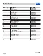
Page 42: ... Lug 05940 200 76 00 4 1 Separator 05700 011 40 05 5 1 Transformer 05950 002 16 78 6 1 Relay 05945 111 35 19 7 2 Contactor 05945 109 05 69 8 1 Access Panel 05700 003 55 38 9 1 Decal Warning Disconnect Power 09905 004 08 16 10 1 Decal Caution 09905 011 68 99 11 1 Terminal Board 05940 002 78 97 12 1 Complete Assembly 05700 004 27 24 1 2 3 4 5 6 7 8 9 10 11 12 ...

Page 43: ...5910 003 43 01 5 1 Ground Lug 05940 200 76 00 6 1 Separator 05700 011 40 05 7 1 Transformer 05950 011 61 67 8 1 Relay 05945 111 47 51 9 2 Contactor 05945 002 74 20 10 1 Access Panel 05700 003 55 38 11 1 Decal Warning Disconnect Power 09905 004 08 16 12 1 Decal Caution 09905 011 68 99 13 1 Terminal Board 05940 002 78 97 14 1 Complete Assembly 05700 003 55 37 1 2 3 4 5 6 9 10 11 12 13 14 7 8 ...

Page 44: ...r Cover 05700 003 57 95 2 1 Bushing 05975 210 03 00 3 1 Access Cover 05700 003 58 73 4 4 Bullet Foot 05340 108 01 03 5 1 Switch Cover 05700 003 60 39 6 1 Power Switch 05930 011 61 69 7 1 Curtain 08415 003 60 35 8 1 Jackson Decal 09905 004 03 02 9 1 Curtain Rod 05700 003 60 38 9 1 2 3 5 6 7 8 ...

Page 45: ...ver and Peri Pump Assembly 05700 003 55 29 3 1 Cover only 05700 003 55 34 4 1 Sanitizer Tube Replacement Kit 06401 003 61 21 5 1 Rinse Aid Tube Replacement Kit 06401 003 61 22 6 1 Detergent Tube Replacement Kit 06401 003 61 23 7 2 Rinse Aid Sanitizer Squeeze Tubes 05700 011 65 21 8 1 Detergent Squeeze Tube 05700 003 22 89 1 3 7 8 2 5 6 ...

Page 46: ...8 22 20 21 19 25 24 23 7 6 5 4 3 2 1 9 10 11 12 13 14 15 16 17 18 Entire Plumbing Assembly 05700 003 58 77 Vacuum Breaker Assembly 05700 003 55 31 Delta 115 has a different part number See parts list on the next page Rinse Tube 05700 003 49 32 ...

Page 47: ...5975 111 62 70 11 2 Solenoid Valve Delta 1200 04730 011 61 54 Solenoid Valve Delta 115 04730 002 75 48 12 2 3 8 Close Nipple 04730 002 18 00 13 2 Union 3 8 NPT Straight Brass 04730 003 60 57 14 2 Tee 3 8 x 3 8 x 3 8 MNPT 04730 011 61 53 15 2 Jam Nut 05310 011 61 45 16 1 Mounting Plate 05700 003 60 21 17 2 Coupling 1 2 FNPT x 3 8 FNPT 04730 011 61 52 18 1 Check Valve 3 8 FNPT 04820 011 61 56 19 1 B...

Page 48: ...610 003 62 15 Q WASH SYSTEM PARTS 8 7 6 5 4 3 2 1 9 10 11 12 13 14 15 16 17 22 20 21 19 23 18 Delta 115 has a different part number See parts list on the next page See previous page Wash Tube 05700 003 49 32 ...

Page 49: ...ump Delta 1200 06105 003 44 22 Wash Pump Delta 115 05700 004 26 50 11 1 Bracket Wash Pump 05700 003 56 41 12 1 Drain Weldment 05700 003 60 00 13 1 Hexnut 1 2 13 S S 05310 011 72 58 14 1 Thermostat Probe 06685 004 17 26 15 1 Washer 1 2 Flat 05311 011 71 93 16 1 Thermostat Probe Fitting 05310 924 02 05 17 1 Thermostat Bracket 05700 004 28 56 18 1 Thermostat ELAN Electronic Dual 06685 004 17 27 19 1 ...

Page 50: ...43 07610 003 62 15 Q PARTS CONVEYOR DRIVE SYSTEM 8 6 5 4 3 2 1 9 10 11 12 13 14 15 16 17 19 18 7 Delta 115 has a different part number See parts list on the next page ...

Page 51: ... 8 1 Washer 05330 003 41 75 9 1 Extension Spring 05340 003 41 83 10 1 Gear Motor Box 05700 003 48 87 11 1 Gear Motor Delta 1200 06105 003 44 23 Gear Motor Delta 115 06105 004 26 30 12 1 Gear Motor Box Cover 05700 003 48 57 13 2 Lock Nut 6 32 05310 373 03 00 14 1 Switch Mounting Bracket 05700 003 60 13 15 1 Liquidtite Fitting 05975 011 49 03 16 1 Limit Switch 05930 303 38 00 17 2 Limit Switch Mount...

Page 52: ...2 24 40 2 1 Handle Door Glasswasher 05340 001 96 30 3 1 Decal Off Fill On 09905 011 61 70 4 2 Hinge 05340 021 62 04 5 8 Starwasher External Tooth 05311 273 02 00 6 8 Screw 10 24 X 3 8 05305 173 03 00 7 1 Decal Operating Instructions 09905 021 64 88 PARTS DOOR ASSEMBLY 4 3 2 1 5 6 7 ...

Page 53: ...46 07610 003 62 15 Q SCHEMATICS DELTA 115 ...

Page 54: ...47 07610 003 62 15 Q SCHEMATICS DELTA 1200 ...

Page 55: ......

Page 56: ...49 Jackson WWS Inc 6209 N US Hwy 25E Gray KY 40734 USA 1 888 800 5672 www jacksonwws com 49 Delta 1200 115 Manual Rev Q 07610 003 62 15 Issued 10 27 08 Revised 9 19 16 ...

Reviews: