background image

SECTION 6: PARTS SECTION

CHEMICAL FEEDER PUMP ASSEMBLY

33

Delta 1200 Technical Manual 07610-003-62-15 C

Issued: 10-27-2008 Revised: N/A

4

Sanitizer Kit

5

Rinse Aid Kit

6

Detergent Kit

7

1

2

3

07610-003-61-19

Summary of Contents for Delta 1200

Page 1: ...NUAL FOR DOMESTIC UNITS FOR JACKSON MODELS Delta 1200 JACKSON MSC INC P O BOX 1060 HIGHWAY 25E BARBOURVILLE KY 40906 FAX 606 523 9196 PHONE 606 523 9795 www jacksonmsc com CHEMICAL SANITIZING GLASSWASHER DISHMACHINE SERIES Feb 10 2010 P N 07610 003 62 15 Revision D ...

Page 2: ......

Page 3: ...DE BY APPLICABLE ECN DETAILS A 10 27 08 CW Initial release of manual B 11 10 08 GS 8074 Revised Drawings C 06 05 09 ARL 90605 1430 MD Updated electrical schematic D 02 10 10 RLC 091106 1526 CW Corrected part number on page 36 i ...

Page 4: ...ii NOMENCLATURE FOR THE MODELS COVERED IN THIS MANUAL GLASSWASHER SERIES Delta 1200 24 Glasswasher Model Serial No Installation Date Service Rep Name Phone No ...

Page 5: ...E 11 IV TROUBLESHOOTING SECTION 13 V MAINTENANCE INSTRUCTIONS Replacing the Chemical Feeder Pump Motor 17 Wash Tank Heater Replacement 20 Thermostat Replacement 23 Wash Motor Replacement 25 VI PARTS SECTION Control Box Assembly 29 Outer Shell Assembly 31 Chemical Feeder Pump Assembly 33 Rinse Assembly 35 Wash Assembly 37 Conveyor and Drive System 39 Door Assembly 41 VII ELECTRICAL DIAGRAM Glasswas...

Page 6: ...1 SECTION 1 SPECIFICATION INFORMATION ...

Page 7: ...tion than what is displayed here Always verify with your electrical service contractor that your circuit protection is adequate and meets all applicable national and local codes These numbers are provided in this manual simply for reference and may change without notice at any given time RINSE TYPICAL HEATER TOTAL ELECTRICAL VOLTS PH HZ RATINGS AMPS CIRCUIT 208 1 60 220V 3KW 15A 15A 230 1 60 220V ...

Page 8: ...ORMATION MACHINE DIMENSIONS 3 B B SECTION B B SCALE 0 09 1 6 59 Drain 12 VERTICAL CLEARANCE A A SECTION A A SCALE 0 09 1 19 45 29 26 2 00 Wall Clearance 12 86 8 64 14 64 25 25 5 00 9 50 25 00 Water Inlet 1 2 I P S Cold Water Inlet 1 2 I P S Hot Ø1 5 Drain Connection 6 17 Inlet 27 41 25 38 05700 003 60 00 ...

Page 9: ...4 SECTION 2 INSTALLATION OPERATION INSTRUCTIONS ...

Page 10: ...HMACHINE The dishmachine is designed to operate while being level This is important to prevent any damage to the machine during operation and to ensure the best results when washing ware The unit comes with adjustable bullet feet which can be turned using a pair of channel locks or by hand if the unit can be raised safely Ensure that the unit is level from side to side and from front to back befor...

Page 11: ...ain line have been installed Check for any leaks and repair as required All leaks must be repaired prior to placing the machine in opera tion ELECTRICAL POWER CONNECTION Electrical and grounding connections must comply with the applicable por tions of the National Electrical Code ANSI NFPA 70 latest edi tion and or other electrical codes Disconnect electrical power supply and place a tag at the di...

Page 12: ... detergent is to be used per cycle Talk with your water treatment specialist and detergent vendor and come up with a complete training program for operators Using too much detergent has as detrimental effects as using too little The proper amount of detergent must be used for job It is important to remember that certain menu items may require extra detergent by their nature and personnel need to b...

Page 13: ...lity and type of detergent It is adjusted by turning the potentiometer on the speed control board clockwise to increase counter clockwise to decrease 5 Rinse additive is dispensed proportionally into the final rinse water line The amount of rinse aid may need to be adjusted depending on water hardness and results It is adjusted by turning the potentiometer on the speed control board clockwise to i...

Page 14: ...rack is able to complete the cycle and is cleaned prior to moving the power switch to the OFF position Shut off the water supply to the unit 2 Remove the drain boards rack cylinder and rack Clean before reinstalling into the machine 3 Remove the sump and drain tank strainers Clean completely before reinstalling into the machine 4 Remove the stand pipe by grasping by the handle and removing from th...

Page 15: ...10 SECTION 3 PREVENTATIVE MAINTENANCE ...

Page 16: ...work harder and decreases efficiency Again it is important to remind operators that trying to perform corrective maintenance on the dishmachine could lead to larg er problems or even cause harm to the operator If a problem is discovered secure the dishmachine using proper shut down procedures as listed in this manual and contact Jackson Some problems however may having nothing to do with the machi...

Page 17: ...12 SECTION 4 TROUBLESHOOTING ...

Page 18: ...l if there is none replace the coil 3 Faulty float switch Ohm out the switch to ensure that upper and lower floats are working If not check float wiring to see if it is correct if so replace float Problem Machine fills continuously even with no power to the dish machine 1 Solenoid valve jammed stuck in the open position Check diaphragm and coil replace as required 2 Faulty float switch Ohm out the...

Page 19: ...ontrol board Check operation of board If not working properly replace Problem Sanitizer pump does not run during cycle but runs when primed Even when turntable is off 1 Loose or broken wire Replace or tighten 2 Faulty speed control board Check operation of board If not working properly replace 3 Faulty prime switch Check continuity through each pole of the speed control board If it fails replace t...

Page 20: ...tube as needed Problem Wash heater does not work Note push wash heater contactor bar down and take amperage reading Amps should be correct as stated on the dish machine data plate 1 If no amp draw check wash heater for continuity If open or shorted replace the heater If closed replace the heater con tactor 2 Wash heater relay will not energize no voltage at contactor coil Check for continuity at w...

Page 21: ...16 SECTION 5 SERVICE PROCEDURES ...

Page 22: ...l be needed to perform this maintenance evolution 1 Phillipshead Screwdriver 2 Needlenose Pliers 3 Wire Cutters 4 Wire Strippers 5 Crimping Tool TIME REQUIRED It is estimated that it will take 1 person thirty minutes per motor to perform this task not including all of the items indicated in the section entitled PREPARATION IMPORTANT NOTES 1 Read these instructions thoroughly before attempt ing thi...

Page 23: ... the cover removed gently pull out the rubber tube from inside the pump 8 Remove the roller by pulling it off of the shaft 9 Using the phillipshead screwdriver remove the four mount ing screws for the motor 10 Once the screws are removed the motor should drop away 11 Cut away any tie wraps that are holding the power wires and remove the motor 12 Take your new motor and attach new terminals to the ...

Page 24: ...on essential personnel are clear of the area restore power to the unit Turn the unit on and by using the priming switch verify that the feeder pump operates and pumps fluid 18 Replace the front door AFTER MAINTENANCE ACTIONS None SPECIAL NOTES Work performed on Jackson dishmachines by unau thorized or unqualified personnel may void the warranty Before beginning this or any other maintenance evolut...

Page 25: ... machine 2 Ensure that incoming water to the machine is secured either by use of a shut off valve or disconnecting the incoming water line 3 The unit must be drained completely with the drain stopper removed TOOLS REQUIRED The following tools will be needed to perform this maintenance evolution 1 3 8 Nutdriver 2 Ratchet 3 1 2 Socket 4 3 8 Socket 5 Torque Wrench 6 Amp Meter TIME REQUIRED It is esti...

Page 26: ...sh tank 8 Once the heater is pushed away from the tank wall pull it out with your hands 9 Remove the old heater gasket and throw away 10 Apply the new heater gasket 11 Take the new heater and slide it through the hole in the wash tank and line it up so the wash tank studs fit in the holes on the heater flange 12 Place the mounting nuts and lockwashers on the studs and secure them with the ratchet ...

Page 27: ... amperage draw to the machine data plate 20 Wait until the heater contactor kicks out meaning that the tub has reached the appropriate temperature and allow the machine to operate approximately ten minutes to verify that there are no leaks and that the heater is maintaining the tank temperature 21 Replace the heater cover 23 Replace the front door AFTER MAINTENANCE ACTIONS Service personnel may wa...

Page 28: ...coming water to the machine is secured either by use of a shut off valve or disconnecting the incoming water line 3 The unit must be drained completely with the drain stopper removed TOOLS REQUIRED The following tools will be needed to perform this maintenance evolution 1 3 8 Nutdriver 2 7 16 Nutdriver 3 7 16 Combination Wrench 4 Needlenose Pliers 5 Phillipshead Screwdriver TIME REQUIRED It is est...

Page 29: ...w the unit to operate nor mally 8 Verify that the thermostat operates the heater contactor Once you have determined the heater contactor is working adjust the wash tank thermostat to ensure that the tempera ture is maintained in accordance with the specifications on the machine data plate 9 Replace the heater cover 10 Replace the front door AFTER MAINTENANCE ACTIONS None SPECIAL NOTES Work perform...

Page 30: ...ut off valve or disconnecting the incoming water line 3 The unit must be drained completely with the drain stopper removed TOOLS REQUIRED The following tools will be needed to perform this maintenance evolution 1 1 4 Nutdriver 2 5 16 Nutdriver 3 Needlenose Pliers 4 7 16 Combination Wrench 5 2 9 16 Combination Wrench TIME REQUIRED It is estimated that it will take 1 person ninety min utes per motor...

Page 31: ...lines 8 Take the needlenose pliers and remove the power wires from the terminals within the motor 9 The motor should now be free Replace with a new new motor by performing the removal steps in reverse 10 Place the disharge hose assembly back on the discharge of the pump and tighten down 11 Lift the assembly into place within the unit ensuring that the suction hose is attached and lines up Move the...

Page 32: ... hose clamp AFTER MAINTENANCE ACTIONS Verify the operation of the new wash motor and pump assembly by running the unit for approximately 15 min utes Check for leaks and corredt as necessary SPECIAL NOTES Work performed on Jackson dishmachines by unau thorized or unqualified personnel may void the warranty Before beginning this or any other maintenance evolution on a unit under warranty you should ...

Page 33: ...28 SECTION 6 PARTS SECTION ...

Page 34: ...Delta 1200 Technical Manual 07610 003 62 15 C Issued 10 27 2008 Revised N A SECTION 6 PARTS SECTION 29 CONTROL BOX ASSEMBLY 14 13 12 11 10 9 8 7 6 5 4 3 2 1 07610 003 61 14 ...

Page 35: ...itting 3 1 05700 003 56 00 Bracket 4 1 05910 003 43 01 Capacitor 5 1 05940 200 76 00 Ground Lug 6 1 05700 011 40 05 Seperator 7 1 05950 011 61 67 Transformer 8 1 05945 111 47 51 Relay 9 2 05945 002 74 20 Contactor 10 1 05700 003 55 38 Access Panel 11 1 09905 100 75 93 Decal Warning Disconnect Power 12 1 09905 011 68 99 Decal Caution 13 1 05975 011 49 03 Terminal Board 14 1 05700 003 56 37 Complete...

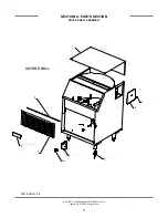
Page 36: ...3 57 95 05700 003 58 73 05975 210 03 00 05700 003 60 39 05930 011 61 69 05340 108 01 03 OUTER SHELL Delta 1200 Technical Manual 07610 003 62 15 C Issued 10 27 2008 Revised N A SECTION 6 PARTS SECTION OUTER SHELL ASSEMBLY 31 1 2 3 4 5 6 7 8 9 07610 003 61 26 ...

Page 37: ...32 Number QTY Part Number Description 1 1 05700 003 57 95 Outer Cover 2 1 05975 210 03 00 Grommett 3 1 05700 003 58 73 Access Cover 4 4 05340 108 01 03 Bullet Foot 5 1 05700 003 60 39 Switch Cover 6 1 05930 011 61 69 Power Switch 7 1 08415 003 60 35 Curtain 8 1 09905 003 57 30 Jackson Decal 9 1 05700 003 57 95 Curtain Rod ...

Page 38: ...ECTION 6 PARTS SECTION CHEMICAL FEEDER PUMP ASSEMBLY 33 Delta 1200 Technical Manual 07610 003 62 15 C Issued 10 27 2008 Revised N A 4 Sanitizer Kit 5 Rinse Aid Kit 6 Detergent Kit 7 1 2 3 07610 003 61 19 ...

Page 39: ...umber QTY Part Number Description 1 1 05700 031 65 20 14 RPM Peri Pump 2 1 05700 003 55 29 Cover and Peri Pump Assembly 3 1 05700 003 55 34 Cover only 4 1 06401 003 61 21 Sanitizer Tube Replacement Kit 5 1 06401 003 61 22 Rinse Aid Tube Replacement Kit 6 1 06401 003 61 23 Detergent Tube Replacement Kit 7 1 05700 011 65 21 Squeeze Tube ...

Page 40: ...003 55 31 04730 011 61 57 05310 011 61 45 05700 003 58 03 04730 011 61 47 06685 011 64 29 06685 111 35 30 05700 003 45 71 05700 003 55 57 05700 003 58 79 05305 011 66 03 05305 031 60 37 09330 003 51 19 04730 002 18 54 04730 011 61 54 05975 111 62 70 09905 011 65 46 04730 002 18 00 04730 003 60 57 05310 011 61 45 05700 003 60 21 04730 011 61 53 04820 011 61 58 04730 002 18 00 04820 011 61 56 04730 ...

Page 41: ...old Mounting Bracket 16 2 05305 011 66 03 10 32 Screw 17 1 05700 031 60 37 Manifold Block 18 1 06685 111 35 30 Thermometer 19 1 05700 003 60 45 Tube 20 2 04730 003 07 07 Elbow 21 1 04710 003 60 46 Tube 22 2 04730 003 60 47 Fitting 23 6 05700 003 55 57 End Cap 24 1 05700 003 49 23 Hose 1 2 ID x 36 Long Polybraid 25 1 05700 003 49 18 Hose 1 2 ID x 45 Long Polybraid 26 1 05700 003 49 23 Fitting 27 1 ...

Page 42: ...ER WASH AND FILL SYSTEM Delta 1200 Technical Manual 07610 003 62 15 C Issued 10 27 2008 Revised N A SECTION 6 PARTS SECTION WASH SYSTEM 37 1 4 5 6 7 2 9 10 11 12 13 14 15 16 17 18 19 20 21 22 23 24 25 26 27 28 29 30 8 2 3 07610 003 61 11 31 ...

Page 43: ...00 10 24 Locknut 12 1 06680 121 70 16 Float 13 1 05700 003 49 27 5 Long Hose 14 1 04730 003 40 64 Pump Hose Connector 15 1 05700 003 59 96 Pump Discharge Hose 16 1 05700 003 60 25 Pump Suction Hose 17 1 06105 003 44 22 Wash Pump 18 1 05305 002 46 43 6 32 x 1 4 Screw 19 1 09905 011 86 86 Ground Decal 20 1 05700 003 60 00 Drain Weldment 21 1 05700 011 71 93 Washier 1 2 Flat 22 1 05310 924 02 05 Ther...

Page 44: ... 05930 011 61 65 05305 171 10 00 05975 011 63 56 05975 011 63 56 05700 003 58 54 09330 003 58 32 05330 003 41 75 05340 003 41 83 05700 003 48 87 06105 003 44 23 05700 003 48 57 09330 003 58 52 05700 003 48 99 05700 003 59 93 09330 003 51 17 05700 005 49 10 09330 003 45 66 CONVEYOR AND DRIVE SYSTEM 1 2 3 4 5 6 7 8 9 10 11 12 13 14 15 16 17 18 19 07610 003 61 13 ...

Page 45: ... Defelctor Wash 6 1 09330 003 58 52 Plate Skid 7 1 09330 003 58 32 Drive Gear 8 1 05330 003 41 75 Washer 9 05340 003 41 83 Extension Spring 10 1 05700 003 48 87 Gear Motor Box 11 1 06105 003 44 23 Gear Motor 12 1 05700 003 48 57 Gear Motor Box Cover 13 2 05975 011 63 56 Strain Relief 14 1 05930 011 61 65 Switch 15 1 05975 011 63 56 Strain Relief 16 1 05930 303 38 00 Limit Switch 17 2 05305 171 10 ...

Page 46: ...Technical Manual 07610 003 62 15 C Issued 10 27 2008 Revised N A SECTION 6 PARTS SECTION DOOR ASSEMBLY 41 05305 173 03 00 05340 021 62 04 05340 001 96 30 07610 003 61 30 09905 021 64 88 09905 011 61 70 1 2 3 4 5 6 ...

Page 47: ...N A SECTION 6 PARTS SECTION DOOR ASSEMBLY 42 Number QTY Part Number Description 1 1 09905 021 64 88 Schematic Decal 2 1 05340 001 96 30 Door Hasp 3 1 07610 003 61 30 Complete Door Assembly 4 1 09905 011 61 70 ON OFF Decal 5 2 05340 021 62 04 Hinge 6 6 05305 173 03 00 Screw ...

Page 48: ...43 SECTION 7 ELECTRICAL SCHEMATICS ...

Page 49: ...Delta 1200 Technical Manual 07610 003 62 15 C Issued 10 27 2008 Revised 06 05 2009 SECTION 7 ELECTRICAL SCHEMATICS 44 ...

Page 50: ......

Reviews: