background image

13

07610-004-43-79-Q

Proper ware preparation helps ensure good results and fewer re-washes. If not done 

properly, ware might not come out clean and efficiency of the dishmachine will be 

reduced. Scraps should always be removed from ware before being loaded into 
a rack. Pre-rinsing and pre-soaking are good ideas, especially for silverware and 
casserole dishes. 

Place cups and glasses upside-down in racks so they don't hold water during the 
cycle. This machine sanitizes as well as cleans. To do this, ware must be properly 
prepared before being placed in machine.

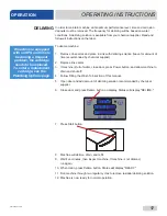
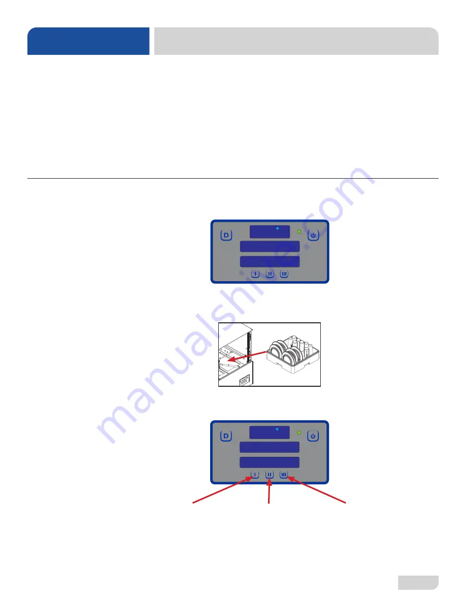
1. Follow the Filling the Wash Tub section, ensuring temperature is at least 155 °F 

and status displays "READY."

2. Open door completely.

3. 

Slide rack into machine.

4. 

Close door.

5. Choose cycle.

WASHING A RACK 

OF WARE

WARE 

PREPARATION

OPERATING INSTRUCTIONS

OPERATION

1 5 5


F

R E A D Y
C Y C L E     1

1 5 5


F

R E A D Y
C Y C L E     1

Cycle I

100 Seconds

Normally-soiled Ware

Cycle II

168 Seconds

Heavily-soiled Ware

Cycle III

268 Seconds

Extremely-soiled Ware

If Cycle II or Cycle III is chosen, machine will stay in that cycle until another is chosen.

Summary of Contents for DISHSTAR HT-E

Page 1: ...E HT E INSTALLATION OPERATION INSTALLATION OPERATION AND SERVICE MANUAL AND SERVICE MANUAL DishStar HT E HT E SEER Manual 07610 004 43 79 Q DISHSTAR DISHSTAR SERIES UNDERCOUNTER DISHMACHINES SERIES UNDERCOUNTER DISHMACHINES ...

Page 2: ...talled by Jackson at the factory and are shipped with the Dishmachine carry only a 1 one year parts warranty Labor to repair or replace these components is not included in the warranty or covered by Jackson Booster heaters not manufactured by Jackson are not covered by this warranty but are warranted by their respective manufacturers This warranty is void if any defect or failure is a direct resul...

Page 3: ...ROM DEFECTS IN MATERIALS AND WORKMANSHIP AND IS REPORTED TO JACKSON WITHIN 30 THIRTY DAYS FROM THE DATE OF INSTALLATION 9 DAMAGE CAUSED BY LABOR DISPUTE 10 DAMAGES RESULTING FROM IMPROPER CONNECTION TO UTILITY SERVICE 11 DAMAGES RESULTING FROM WATER CONDITIONS INADEQUATE OR EXCESSIVE WATER PRESSURE ACCIDENTS ALTERATIONS IMPROPER USE ABUSE HANDLING OVERLOADS TAMPERING IMPROPER INSTALLATION OR FAILU...

Page 4: ...in water tempering kit and 460 V drain water tempering kit to pg 57 Updated schematics on pgs 58 59 G 4 24 19 JH 19 553 Updated 208 230 V schematic H 5 4 20 JH 8664 8709 8721 19 730 Revised Programming Chemical Feeder Pumps section Updated pump assemblies on pgs 38 39 Added drip shield and gasket to pg 39 Updated P N for item 12 on pg 57 Added wash heater gasket to pg 59 Updated SEER System pages ...

Page 5: ...Elimination and Energy Recovery System SEER The manufacturer provides technical support for all of the dishmachines detailed in this manual We strongly recommend that you refer to this manual before making a call to our technical support staff Please have this manual open when you call so that our staff can refer you if necessary to the proper page Technical support is not available on holidays Co...

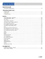
Page 6: ...e Regulator 8 Shock Absorber 8 Connecting the Drain Line 8 Plumbing Check 8 Electrical Power Connections 9 Motor Rotation 9 Voltage Check 10 Surrounding Area 10 Temperature Setpoints 10 Leveling 10 Chemical Feeder Equipment 10 Preparing Chemical Feeder Pumps 11 Priming Chemical Feeder Pumps 11 Operating Instructions 12 Preparation 12 Power Up 12 Filling the Wash Tub 12 Ware Preparation 13 Washing ...

Page 7: ... 230 V 33 HT E Control Panel 460 V 34 HT E SEER Control Panel 460 V 35 Chemical Feeder Pumps 460 V 36 Door 38 Miscellaneous Door Components 40 HT E SEER Door Interlock 208 230 V 41 HT E SEER Door Interlock 460 V 42 Wash 43 Motors 45 Rinse 46 Plumbing Options 47 HT E Plumbing 48 HT E SEER Plumbing 50 Rinse Plumbing 52 Rinse Tank 54 SEER System 56 Stands Panels 58 Frame 59 Miscellaneous Parts 60 SCH...

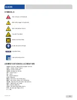
Page 8: ...s MCA Minimum Circuit Ampacity MOP Maximum Overcurrent Protection NFPA National Fire Protection Association NPT National Pipe Thread OD Outside Diameter PRV Pressure Regulating Valve PSI Pounds per Square Inch V Volts CAUTION WARNING NOTICE Risk of Injury to Personnel Risk of Damage to Equipment Risk of Electrical Shock Lockout Electrical Power Reference Data Plate Important Note i Caustic Chemica...

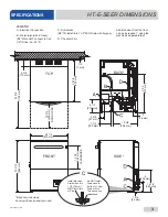
Page 9: ... 16 846 mm 14 1 4 362 mm CLEARANCE LEGEND A Electrical Connection B Water Inlet with 6 Hose 3 4 Male GHT connect to true 1 2 ID line MIN 110 F C Drain Hose 5 8 ID install into 1 1 2 MIN Drain with Air gap All dimensions from the floor can be increased 1 using the machine s adjustable feet Install Machine Drain Hose into 1 1 2 38 mm MIN Floor Drain or Sink Do NOT install Drain Hose to bottom of Flo...

Page 10: ...4 210 mm Back and side views shown with back panel removed LEGEND A Electrical Connection B Water Inlet with 6 Hose 3 4 Male GHT connect to true 1 2 ID line 40 90 F C Drain Hose 5 8 ID install into 1 1 2 MIN Drain with Air gap All dimensions from the floor can be increased 1 using the machine s adjustable feet D Chemical Port Install Machine Drain Hose into 1 1 2 38 mm MIN Floor Drain or Sink Do N...

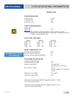
Page 11: ...e 110 Other Water Requirements Water Flow Pressure PSI 10 Flow Rate Minimum GPM 4 33 Water Line Size NPT 3 4 Male GHT Connect to true 1 2 ID Line Drain Line Size NPT 5 8 ID Connect to MIN 1 1 2 Drain with Air gap Gallons per Hour GPH 21 6 16 2 Gallons per Rack GPR 0 60 Racks per hour calculated with NSF suggested load time of 30 for front opening dishmachines Gallons per hour calculated with NSF s...

Page 12: ...perature 90 Other Water Requirements Water Flow Pressure PSI 10 Flow Rate Minimum GPM 4 33 Water Line Size NPT 3 4 Male GHT Connect to true 1 2 ID Line Drain Line Size NPT 5 8 ID Connect to MIN 1 1 2 Drain with Air gap Gallons per Hour GPH 14 4 12 0 Gallons per Rack GPR 0 60 Racks per hour calculated with NSF suggested load time of 30 for front opening dishmachines Gallons per hour calculated with...

Page 13: ...ailable Electrical Characteristics 208 V 60 Hz Single phase 230 V 60 Hz Single phase 460 V 60 Hz Three phase Available Wash Motors 1 HP Available Wash Tank Heaters 3 3 kW 208 V 4 0 kW 230 V 3 7 kW 460 V Available Rinse Tank Heaters 4 1 kW 208 V 5 2 kW 230 V 5 0 kW 460 V DishStar HT E HT E SEER Electrical Characteristics VOLTS 208 230 460 PHASE 1 1 3 FREQ 60 60 60 WASH MOTOR AMPS 5 0 A 5 0 A 2 0 A ...

Page 14: ...rials from cutting processes can become lodged in the solenoid valves and prevent them from opening or closing Any valves that are found to be fouled or defective because of foreign matter left in the water line and any subsequent damage are not the responsibility of the manufacturer See the HT E Dimensions or HT E SEER Dimensions page depending on your model and reference item B for water inlet c...

Page 15: ...n of a shock absorber on the incoming water line and offers them as an option see the Plumbing Options page A shock absober comes standard on the HT E SEER This prevents water hammer or hydraulic shock induced by the solenoid valve as it operates from causing damage to the equipment The machine has a pumped pressure drain capable of pumping waste water to a height of 24 above the floor to the kitc...

Page 16: ... so can result in damage to machine and components 1 Follow Filling the Wash Tub section 2 Using a 7 16 nutdriver remove front kick panel and keep hardware Using a phillips screwdriver remove right dress panel and keep hardware Leave start switch wires connected 3 Locate wash pump motor and identify arrow decal which shows correct motor rotation 4 Press Start button on right dress panel and immedi...

Page 17: ...e terminal block box cover and tighten down the screws This is a commercial machine and reaches temperatures that can exceed those generated by a residential machine Surrounding countertops cabinets flooring material and subflooring material must be designed and or selected with these higher temperatures in mind CAUTION Damage to materials not recommended for higher temperatures will not be covere...

Page 18: ...to stop priming cycle If not enough run priming cycle again 3 To prime rinse aid pump press and hold II button until display shows timer Priming cycle defaults to 180 seconds 4 Detergent amount might need adjusted depending on water quality and type of detergent Rinse aid amount might need adjusted depending on water hardness and results Refer to next section for instructions on adjusting chemical...

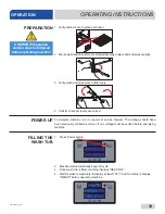
Page 19: ...rvice breaker The voltage should have been previously verified as correct If not voltage must be verified before energizing machine 1 Press Power button 2 Machine will automatically begin fill cycle 3 Once wash tub is filled machine displays HEATING 4 Wait for wash temperature to display at least 155 F and for status to display READY before operating machine PREPARATION POWER UP FILLING THE WASH T...

Page 20: ...e cycle This machine sanitizes as well as cleans To do this ware must be properly prepared before being placed in machine 1 Follow the Filling the Wash Tub section ensuring temperature is at least 155 F and status displays READY 2 Open door completely 3 Slide rack into machine 4 Close door 5 Choose cycle WASHING A RACK OF WARE WARE PREPARATION OPERATING INSTRUCTIONS OPERATION 155 F READY CYCLE 1 1...

Page 21: ...After sanitize cycle is complete machine will automatically go back to being READY Open door and remove rack of ware To start another cycle load another rack of ware close door and push Start button 155 F WASHING CYCLE 1 OPERATING INSTRUCTIONS OPERATION WASHING A RACK OF WARE 180 F RINSING 10 PSI Temperature shown is minimum required temperature Temperature shown is minimum required temperature SA...

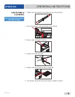
Page 22: ...m obstruction If clogged remove end caps clean nozzles with a brush and flush with fresh water OPERATIONAL INSPECTION SHUTDOWN CLEANING OPERATING INSTRUCTIONS OPERATION Based on use strainers might become clogged with soil and debris as the workday progresses Operators should regularly inspect strainers to ensure they ve not become clogged Clogged strainers will reduce washing capability of machin...

Page 23: ...ft strainer is free of debris 8 Spray or wipe out interior of machine 9 Replace wash and rinse arms 10 Replace strainers and ensure they are laying flat 11 Use stainless steel polish to clean and protect outside of machine OPERATING INSTRUCTIONS OPERATION SHUTDOWN CLEANING Use a screwdriver to ensure end caps are tight ...

Page 24: ...machine to drain and shut off 4 Follow Filling the Wash Tub section of this manual 5 Open door and add amount of deliming solution recommended by chemical supplier 6 Close door and press Delime button on display Status will display DELIME 7 Press Start button 8 Machine will delime drain and refill 9 Wait five minutes then inspect machine If machine is not delimed run again 10 When clean press Deli...

Page 25: ...for the water going to the machine only Discuss this option with a qualified water treatment specialist Properly train operators on how much detergent is to be used per cycle Meet with a water treatment specialist and chemical supplier to discuss a complete training program for operators Water temperature is an important factor in ensuring the machine functions properly and the machine s data plat...

Page 26: ...AINTENANCE i XXXXXXXXX ATTENSION SE CONNECTER A UN MINIMUM D ALIMENTATION 30 AMPERES DELAI FUSIBLE DE TYPE NON TEMPS OU LA PROTECTION CONTRE LES SURINTENSITES NOTE WASH AND RINSE HEATER DO NOT OPERATE AT THE SAME TIME ELECTRICAL LOADS BASED ON WASH MOTOR AND RINSE HEATER HIGHEST AMP DRAW CAUTION IF THIS MACHINE IS CONNECTED TO A CIRCUIT PROTECTED BY FUSES U S E O N LY 3 0 A N O N T I M E D E L AY ...

Page 27: ...entrations 8 Clean machine at end of every workday see Shutdown and Cleaning section 9 If hard water is present install an SPS into water line connecting to machine see Water Supply Connections section 10 Always contact a qualified service agency when a serious problem arises 11 Follow all safety procedures whether listed in this manual or put forth by local state or national codes regulations PRE...

Page 28: ...ram number must be correct to ensure machine works properly To confirm program number 1 Press and hold I and III buttons until Program flashes 2 3 seconds 2 Confirm bottom display shows 8 If not contact a qualified service agency 3 Press Delime button to exit PROGRAM PROGRAM 8 READY CYCLE 1 150 F TROUBLESHOOTING PROGRAMMING ...

Page 29: ...will be flashing Language Wash Offset Temperature Scale Rinse Offset Wash Temperature Boost Offset Boost Temperature Spare Offset 4 Press Select button to choose category to change Regardless of category Steps 5 7 remain the same 5 Use Up arrow button to change options will be flashing Numerical options are shown in top window 6 Press Select button to accept changes 7 Press Delime button to exit U...

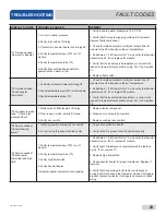
Page 30: ...Ω resistor for T3 and verify that booster heater turns off If not replace IO module 3 Verify that the booster probe resistance is correct with respect to temperature see table on pg 24 If not replace T3 F3 No water in wash tank Check inlet water and door 1 Malfunction of fill solenoid or fill relay 2 Door is open which inhibits fill mode 3 Faulty door switch 1 Replace faulty component 2 Close door...

Page 31: ...t to temperature see table on pg 24 If not replace T1 F8 No water in wash tank Check inlet water and door 1 Malfunction of fill solenoid or fill relay 2 Door is open which inhibits fill mode 3 Faulty door switch 1 Replace faulty solenoid or fill relay 2 Close door to activate door switch 3 Replace or adjust door switch DISPLAY SHOWS POSSIBLE CAUSES REMEDY F9 Service needed Check incoming power 1 I...

Page 32: ...od display board and check if F13 message recurs If so repeat substitution with a good I O module F14 Service needed Check incoming water pressure or pressure switch 1 Low or no water pressure 2 Faulty pressure switch 3 Faulty fill valve or fill valve not receiving power 1 Verify correct PSI 2 Replace pressure switch 3 Check continuity and replace if faulty F15 Sanisure violation 1 Faulty booster ...

Page 33: ...nect or replace wires in motor 2 Adjust button or replace 3 Replace Little or no water coming through the rinse assemblies 1 Limed up rinse heads or piping 2 Low water pressure 1 Delime rinse heads 2 Increase pipe size to machine Adjust pressure regulating valve WARNING Inspection testing and repair of electrical equipment should only be performed by qualified service personnel Certain procedures ...

Page 34: ...heck amperages Replace if necessary 4 Adjust rinse tank setpoint Machine doesn t drain when power button is pressed 1 Drain clogged 2 Defective drain valve 1 Remove obstruction 2 Replace Incorrect water pressure displayed during Fill or Rinse 1 Water turned off 2 Transducer disconnected 3 Pressure transducer defective 1 Turn water on 2 Verify wiring 3 Replace pressure transducer TROUBLESHOOTING TR...

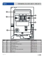
Page 35: ...36 47 1 Terminal Box Cover Not Shown 05700 003 27 70 3 1 Strain Relief 05975 003 37 56 4 1 Terminal Block Track 05700 000 43 60 5 2 Terminal Block 05940 500 02 19 6 2 Locknut 10 24 Hex with Nylon Insert 05310 373 01 00 7 1 Decal L1 N 09905 011 62 72 8 1 Ground Lug 05940 200 76 00 6 7 5 4 8 1 3 2 TERMINAL BLOCK BOX 208 230 V PARTS ...

Page 36: ...0 004 44 79 1 Terminal Box Cover Not Shown 05700 004 44 80 3 1 Strain Relief 05975 210 03 00 4 1 Terminal Block Track 05700 004 44 72 5 3 Terminal Block 05940 500 02 19 6 2 Locknut 8 32 Low Profile 05310 004 23 83 7 1 Decal L1 L2 L3 09905 101 12 66 8 1 Ground Lug 05940 200 76 00 6 7 5 4 8 1 3 2 TERMINAL BLOCK BOX 460 V PARTS ...

Page 37: ...373 03 00 3 2 P clamp 1 4 ID 05975 002 61 42 4 1 Bushing Snap 05975 210 09 00 5 4 Locknut 10 24 Hex with Nylon Insert 05310 373 01 00 6 1 Cover Display 05700 004 46 05 7 4 Nut Thumb 6 32 Nylon 05310 002 83 12 8 1 PCB Digital Display 05700 004 19 47 9 4 Spacer Unthreaded 9 32 Nylon 05975 004 47 89 10 1 Panel Membrane Switch Assembly 05700 004 58 72 11 1 Communication Cable 05700 004 33 64 11 ...

Page 38: ...230 V PARTS 12 2 18 23 24 16 17 26 25 11 17 16 15 14 9 6 7 28 10 27 8 19 27 3 3 29 30 31 34 33 32 22 1 13 21 4 5 20 L2 L1 208 230 V machines with serial numbers before 22E406186 have a universal timer Click here to open earlier manual NOTICE ...

Page 39: ...A 250 V 05920 004 85 54 16 5 Nut Plated 6 32 05340 118 04 00 17 3 Screw 6 32 x 3 8 05305 002 25 91 18 2 Screw 10 32 x 1 05305 002 19 42 19 1 Peri pump Assembly 38 RPM 05700 005 00 29 20 2 Jumper Bars 4 Pole 05999 004 41 80 21 2 Jumper Bars 3 Pole 05999 004 90 71 22 1 Jumper Bars 2 Pole 05999 004 41 79 23 1 Screw 10 32 x 1 2 05305 011 39 36 24 1 Decal Ground 09905 011 86 86 25 1 Fuser Holder One On...

Page 40: ... 07 5 4 Screw 8 32 x 1 2 Phillips 05305 111 37 06 6 2 Roller Black Dot 04320 111 65 27 7 1 Tube Squeeze 14 RPM Peri pump 04320 004 92 38 8 2 Pump Cover Clear 04320 004 59 45 9 6 Screw 6 32 x 3 4 Phillips 05305 011 37 05 10 1 Motor 38 RPM 04320 004 99 36 11 1 Tube Squeeze 36 RPM Peri pump 05700 003 22 89 Part numbers for complete assemblies on previous page 208 230 V machines with serial numbers be...

Page 41: ...actor 05940 111 60 30 4 1 Dinrail 7 3 4 05700 002 79 13 5 6 Screw 10 32 x 5 8 05305 003 02 12 6 1 Motor Overload 1 35 2 A 05945 111 60 08 7 3 Screw 10 32 x 1 05305 002 19 42 8 1 I O Module 06401 004 76 15 9 1 Terminal Board 05940 004 21 34 10 1 Terminal Board 05940 002 78 97 11 1 Relay 05945 002 47 41 12 3 Screw 6 32 x 3 8 05305 002 25 91 13 1 Fuse Holder 05920 011 72 89 14 1 Fuse 1 2 A 05920 011 ...

Page 42: ... 05940 004 21 34 5 9 Fastener 05340 111 58 10 6 6 Nut Plated 05340 118 04 00 7 3 Screw 10 32 x 1 05305 002 19 42 8 6 Screw 10 32 x 5 8 05305 003 02 12 9 6 Screw 6 32 x 3 8 05305 002 25 91 10 3 Contactor 460 V 05945 111 60 07 11 1 Motor Overload 1 35 2 A 05945 111 60 08 12 2 Relay 05945 002 47 41 13 2 End cap Contactor 05940 111 60 30 14 1 Dinrail 7 3 4 05700 002 79 13 15 1 Fuse 1 2 A 05920 011 72 ...

Page 43: ...07610 004 43 79 Q 36 PARTS CHEMICAL FEEDER PUMPS 460 V Complete Peri pump Panel Assembly 460 V 05700 004 44 45 1 2 3 6 5 4 8 7 9 10 11 12 13 20 15 14 17 16 18 19 21 22 23 ...

Page 44: ...ete Peri pump Assembly 14 RPM 115 V for 460 V machine 05700 004 78 21 1 Motor Only Peri pump 14 RPM 115 V for 460 V Machine 04320 111 35 13 9 1 Panel Outer Control 05700 004 41 89 10 2 Pump Housing Clear 04320 004 59 41 11 1 Roller Red Dot 04320 111 36 70 12 1 Tube 8 04320 004 92 38 13 2 Pump Cover Clear 04320 004 59 45 14 1 Tube 8 05700 111 35 29 15 1 Roller Black Dot 04320 111 65 27 16 4 Locknut...

Page 45: ...07610 004 43 79 Q 38 DOOR PARTS 1 66 0 Complete Door Assembly 05700 004 36 53 ...

Page 46: ...9 2 Stop Door Hinge 05700 003 32 55 10 1 Hinge Left 05700 003 32 71 11 1 Hinge Right 05700 003 32 72 12 1 Inner Door 05700 003 33 21 13 1 Baffle Door 05700 003 33 38 14 2 Hinge Spacer 05700 003 33 42 15 1 Switch Assembly 05700 003 34 80 16 2 Retaining Plate 05700 011 44 37 17 1 Channel Door Seal 05700 003 55 49 18 6 Screw 1 4 20 x 1 1 2 Hex Head 05305 274 23 00 19 1 Gasket Door L 05330 004 36 05 2...

Page 47: ...700 004 36 80 4 1 Cover Right Hinge Weldment 05700 004 36 81 Hinges secured with Locknut 1 4 20 Hex with Nylon Insert 05310 374 01 00 5 2 O ring 05330 003 32 34 6 2 Latch Spring 05340 004 67 82 7 4 Latch Nut 05700 003 32 33 8 2 2 Locknut 6 32 Hex with Nylon Insert Screw 6 32 x 1 4 05310 373 03 00 05305 171 01 00 9 1 Door Switch 05930 003 31 44 10 1 1 Door Switch Bracket Door Switch Bracket Assembl...

Page 48: ... Interlock 05930 004 71 36 6 1 Synchronous Gearmotor 6 RPM 230 V 60 Hz 06105 004 70 04 7 1 Interlock Guide 05700 004 71 50 8 1 Interlock Cam 05700 004 71 39 9 2 Shoulder Screw 10 32 05700 004 71 40 10 1 Bracket Interlock 05700 004 99 63 11 2 Screw 10 32 x 1 2 05305 011 39 36 12 2 Locknut 10 32 with Nylon Insert 05310 373 02 00 13 1 Set Screw 6 32 x 1 4 05305 004 71 42 2 2 1 5 5 11 4 7 13 3 8 1 1 9...

Page 49: ...00 004 47 51 3 1 Bearing Dry Running Sleeve 1 4 ID 03120 004 47 52 4 1 Locknut 1 4 20 Low Profile with Nylon Insert 05310 374 02 00 5 1 Bracket Solenoid 05700 004 50 99 6 1 Bracket Solenoid Guide 05700 004 51 00 7 4 Screw 6 32 x 1 8 Pan Head Phillips 05305 004 51 01 8 1 Spring Conical Compression 05340 004 47 53 9 1 Guide Plate Door Interlock 05700 004 47 40 Item not included in part number of com...

Page 50: ...43 07610 004 43 79 Q WASH PARTS 3 4 5 5 6 5 1 2 7 5 5 10 11 12 13 13 15 15 16 16 15 17 18 19 8 9 13 13 14 ...

Page 51: ...05700 004 43 04 10 1 Wash Motor See Motors page 11 1 Discharge Hose 7 8 x 8 05700 004 43 76 12 1 Hose 1 1 4 x 2 3 4 05700 011 44 48 13 4 Clamp 1 1 16 to 2 04730 719 18 00 14 1 Hose Manifold Bottom 05700 001 22 92 15 3 Clamp 13 16 to 1 1 2 04730 719 06 09 16 2 Hosebarb 90 Degree 3 4 x 1 04730 011 65 87 17 1 Drain Valve Assembly 208 230 V 04730 003 33 64 1 Drain Valve Assembly 115 V for 460 V Machin...

Page 52: ... 002 81 87 05700 002 06 22 3 1 Case O ring 208 230 V Case O ring 460 V 05330 002 81 83 05330 002 87 02 4 1 Mechanical Seal 208 230 V Mechanical Seal 460 V 05330 002 34 22 05330 002 87 16 5 1 Impeller Assembly 208 230 V Impeller Assembly 460 V 05700 002 81 86 05700 002 06 19 6 1 Pump Casing 208 230 V Pump Casing 460 V 05700 002 85 01 05700 002 06 20 7 1 Case Capscrew 05305 002 81 88 1 2 3 5 4 6 7 ...

Page 53: ...5 06 3 4 Rinse Arm End cap includes o ring 05700 004 34 62 4 2 Complete Rinse Arm Assembly 05700 004 39 39 2 Rinse Arm 05700 004 38 75 5 2 Bearing Assembly Rinse Arm 05700 004 54 71 6 2 O ring included in item 5 05330 002 60 69 7 2 Retaining Ring 05340 112 01 11 Rinse Arm Bearing Kit 06401 004 57 50 RINSE PARTS 1 2 3 4 3 3 3 4 5 7 6 ...

Page 54: ... 04730 003 28 04 SPS System 04730 003 28 03 Replacement Test Strip Not Shown 06401 003 28 06 Must be installed vertically The provided bracket is secured to the wall Observe proper inlet outlet water directions flow directions are molded into the top of the head Line pressure should be released before changing cartridges Machine should be delimed before installation NOTICE SCALE PREVENTION SYSTEM ...

Page 55: ... 6 5 4 3 2 7 1 Complete Inlet Plumbing Assembly 208 230 V 05700 004 09 03 Complete Inlet Plumbing Assembly 115 V for 460 V Machine 05700 004 44 40 8 Item not included in part number of complete plumbing assembly and must be ordered separately ...

Page 56: ... 04730 003 62 44 3 1 Nipple 1 2 Close Brass 04730 207 15 00 4 1 Nipple 1 2 x 4 NPT Brass 04730 207 04 00 5 1 Adapter 1 2 Fitting Male 04730 011 59 53 6 1 Elbow 1 2 04730 406 31 01 7 1 Hose Adapter 04720 004 24 68 8 1 Bracket Plumbing Support 05700 004 56 19 HT E PLUMBING PARTS Item not included in part number of complete plumbing assembly and must be ordered separately ...

Page 57: ...30 V 05700 004 63 79 Complete SEER Plumbing Assembly 460 V 05700 004 78 45 3 9 8 7 6 4 5 2 1 10 CONNECTS TO HOT WATER OUTLET ON SEER SYSTEM CONNECTS TO COLD WATER INLET ON SEER SYSTEM 11 Item not included in part number of complete SEER plumbing assembly and must be ordered separately ...

Page 58: ...ly 05700 004 55 97 4 1 Tee 1 2 Brass 04730 211 27 00 5 1 Nipple 1 2 Close Brass 04730 207 15 00 6 1 Water Hammer Arrestor 1 2 04730 004 58 56 7 1 SEER Inlet Plumbing Assembly 05700 004 60 46 8 1 Elbow 90 degree 1 2 Street Brass 04730 206 08 00 9 1 Adapter Double Male 3 4 11 5 x 1 2 14 04720 004 51 55 10 1 Inlet Hose Assembly 05700 004 71 02 11 1 Bracket Plumbing Support 05700 004 56 19 Item not in...

Page 59: ...07610 004 43 79 Q 52 1 2 4 5 6 7 3 8 9 RINSE PLUMBING PARTS 8a 8d 8e 8h 8f 8g 8c 8b Complete Rinse Plumbing Assembly 05700 004 43 02 ...

Page 60: ... 32 01 6 1 Pipe 4 3 4 Copper 05700 002 91 02 7 1 Adapter 1 2 04730 002 64 68 8 8a 8b 8c 8d 8e 8f 8g 8h 1 1 1 2 1 1 1 2 1 Complete Rinse Injector Assembly Rinse Injector Only Gasket Rinse Injector Screw 1 4 20 x 1 Check Valve Fitting Outlet Elbow Nut Tube 1 8 Plug 1 8 Brass Pressure Transducer 05700 004 43 86 09515 004 22 73 05330 003 75 91 05305 011 81 58 04820 111 51 14 04820 111 51 18 04730 011 ...

Page 61: ...07610 004 43 79 Q 54 RINSE TANK PARTS 1 2 3 4 5 6 7 8 9 10 11 6 7 13 14 15 12 16 ...

Page 62: ...7 2 Thermistor Probe 4 with 18 Cable 06685 004 34 58 8 1 Fitting 1 4 Brass Nut Sleeve 05310 924 02 05 9 1 Plug 1 4 Brass 04730 209 01 00 10 1 Union 1 2 x 1 2 Brass 04730 003 62 44 11 1 Elbow 90 degree 1 2 Street Brass 04730 206 08 00 12 1 Nipple 1 2 Close Brass 04730 207 15 00 13 1 Fitting 1 2 x 1 4 05700 004 36 74 14 1 Tee 1 2 Brass 04730 211 27 00 15 1 Nipple 1 2 x 3 Brass 04730 004 20 10 16 1 E...

Page 63: ...8 19 20 STICKY SIDE Complete SEER System Assembly 208 230 V 05700 004 63 06 Complete SEER System Assembly 115 V for 460 V Machine 05700 004 64 72 Machines with serial numbers before 19G376587 have an older version of the SEER System Click here to open manual with the older version NOTICE ...

Page 64: ...00 004 58 93 9 1 Diversion Plate 05700 004 59 04 10 1 Upper Shield 05700 004 58 98 11 1 Heat Exchanger 3 8 Tubes 04420 004 58 96 12 12 Locknut 1 4 20 Hex with Nylon Insert 05310 374 01 00 13 8 Screw 6 32 x 1 2 05305 004 23 63 14 1 Condenser Assembly 05700 004 58 94 15 2 Bolt 1 4 20 x 1 2 05305 274 02 00 16 1 Plumbing SEER Inlet 05700 004 60 46 17 1 Bracket Bearing Hard Stop 05700 004 67 53 18 1 Lo...

Page 65: ...05340 108 01 03 5 1 18 Stand Assembly 05700 003 34 25 6 1 Stand 05700 002 88 82 7 4 Bullet Foot 05340 108 01 03 8 4 18 Leg 05700 002 89 47 9 4 Cross Brace 05700 003 25 90 10 4 Cross Member Bracket 04730 003 25 89 11 11a 1 3 Back Panel Edge Guard Back Panel Not Shown 05700 004 58 14 05330 002 83 04 1 2 3 4 5 10 9 8 7 6 6 Stand Install Instructions 18 Stand Install Instructions 11 ...

Page 66: ...Left 05700 003 31 91 3 4 Adjustable Foot 05340 002 71 71 4 1 Shroud Top 05700 003 37 06 5 1 Frame Right 05700 003 31 90 6 2 Plug Shroud 05700 003 32 50 7 1 Panel Bottom 05700 004 44 54 8 1 Support Strainer Left 05700 004 40 52 9 1 Support Strainer Right 05700 004 40 53 10 2 Strainer 05700 004 09 43 11 1 Shroud Right 05700 004 36 82 ...

Page 67: ...6685 004 34 58 7 1 Probe Fitting 1 4 Brass 05310 924 02 05 8 1 Wash Heater 4 kW 208 230 V Wash Heater 4 kW 460 V Gasket Wash Heater Not Shown 04540 003 99 44 04540 004 12 29 05330 011 61 34 9 1 Thermostat Wash Tank High limit with Compression Fitting 05930 004 33 15 10 1 Transformer 460 V 05950 011 50 70 11 1 Transformer Bracket 460 V 05700 004 44 55 4b Parts are not shown to scale in relation to ...

Page 68: ...61 07610 004 43 79 Q SCHEMATICS 208 230 V 50 60 HZ 1 PHASE 208 230 V machines with serial numbers before 22E406186 have a different schematic Click here to open earlier manual NOTICE ...

Page 69: ...el AC power in K 1 K2 L1 L2 N Input Assignments I1 Wash I2 Cycle I3 Float I4 Rinse I5 Door Chemicals BLK DC RTN RED 24 VDC WHT BLK DC RTN VDC OUT CORRESPONDING CONNECTOR TO DISPLAY PCB PN 05945 004 36 33 B L K B L K R E D W H T B L K G R N LOGIC INPUT VDC OUT T3 GRN BLK K 2 K 3 K 4 K 5 K 6 K 7 K 8 K 9 K 10 K 11 K 12 Interconnect cable is Belden 9745 060U500 3 twisted pairs Connection Diagram for I...

Page 70: ...Jackson WWS Inc 6209 N US Hwy 25E Gray KY 40734 USA 1 888 800 5672 www jacksonwws com DishStar HT E HT E SEER Manual 07610 004 43 79 Q ...

Reviews: