background image

07610-004-99-71-B

38

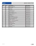
ITEM

QTY

DESCRIPTION

PART NUMBER

1

1

Wash Arm Assembly

05700-021-39-23

2

1

Motor Support

05700-004-53-96

3

1

Wash Halo

05700-004-42-21

4

2

Pipe Clamp

05700-000-35-06

5

5

Wash Arm End-cap

05700-003-31-59

6

1

Gasket, Manifold

05330-003-75-91

7

1

Hose, 5/8" ID, Blue Silicone

05700-004-53-99

8

1

Gasket, Wash Hub

05330-002-34-77

9

1

Wash Hub

05700-004-43-04

10

1

Pump and Motor

06105-004-50-75

11

1

Hose, 7/8" ID x 8", Blue Silicone

05700-004-43-76

12

1

Hose, Bottom Manifold Pump

05700-001-22-92

13

2

Clamp, 1 1/16" to 2"

04730-719-18-00

14

1

Hose, 1 1/4" ID x 4", Blue Silicone

05700-004-54-00

15

7

Clamp, 13/16" to 1 1/2"

04730-719-06-09

16

2

Hosebarb, 1 3/4"

04730-011-65-86

17

1

Drain Valve Assembly

04730-003-33-64

18

1

Drain Hose

04720-004-32-00

19

1

Bracket, Soft Starter

05700-004-55-94

20

1

Soft Starter

05945-004-55-75

WASH & MOTOR

PARTS

Summary of Contents for DishStar Series

Page 1: ...STAR ADA SEER INSTALLATION OPERATION INSTALLATION OPERATION AND SERVICE MANUAL AND SERVICE MANUAL DishStar ADA SEER Manual 07610 004 99 71 B DISHSTAR DISHSTAR SERIES GLASSWASHER DISHMACHINES SERIES GL...

Page 2: ...alled by Jackson at the factory and are shipped with the Dishmachine carry only a 1 one year parts warranty Labor to repair or replace these components is not included in the warranty or covered by Ja...

Page 3: ...OM DEFECTS IN MATERIALS AND WORKMANSHIP AND IS REPORTED TO JACKSON WITHIN 30 THIRTY DAYS FROM THE DATE OF INSTALLATION 9 DAMAGE CAUSED BY LABOR DISPUTE 10 DAMAGES RESULTING FROM IMPROPER CONNECTION TO...

Page 4: ...Letter Revision Date Made by Applicable ECNs Details A 12 13 21 JH 8566 Initial release of the manual B 2 2 22 JH 8709 Updated electical panel chemical feeder pump assembly and door interlock REVISION...

Page 5: ...ical support for all of the dishmachines detailed in this manual We strongly recommend that you refer to this manual before making a call to our technical support staff Please have this manual open wh...

Page 6: ...Regulator 6 Shock Absorber 6 Connecting the Drain Line 6 Plumbing Check 6 Electrical Power Connections 7 Voltage Check 7 Surrounding Area 7 Temperature Setpoints 7 Leveling 7 Chemical Connections 8 Pr...

Page 7: ...nal Block Box 26 Top Panel 27 Electrical Panel 28 Chemical Feeder Pump Assembly 30 Door 32 Door Interlock 34 Miscellaneous Door Components 36 Wash Motor 37 Rinse Manifold 39 Plumbing 40 Rinse Plumbing...

Page 8: ...MCA Minimum Circuit Ampacity MOP Maximum Overcurrent Protection NFPA National Fire Protection Association NPT National Pipe Thread OD Outside Diameter PRV Pressure Regulating Valve PSI Pounds per Squ...

Page 9: ...l Port All dimensions from the floor can be increased 1 using the machine s adjustable feet Back and side views shown with back panel removed 14 356 mm DOOR OPEN 26 7 8 692 mm 1 4 7 mm 40 7 8 1037 mm...

Page 10: ...r Temperature 40 Maximum Incoming Water Temperature 90 Other Water Requirements Water Flow Pressure PSI 10 Flow Rate Minimum GPM 4 0 Water Line Size NPT 3 4 Male GHT Connect to true 1 2 ID Line Drain...

Page 11: ...data plate The electrical configurations are as follows Available Electrical Characteristics 208 V 60 Hz Single phase 230 V 60 Hz Single phase Available Wash Motors 3 4 HP Available Wash Tank Heaters...

Page 12: ...sses can become lodged in the solenoid valves and prevent them from opening or closing Any valves that are found to be fouled or defective because of foreign matter left in the water line and any subs...

Page 13: ...ring the cycle A shock absober comes standard on the DishStar ADA SEER This prevents water hammer or hydraulic shock induced by the solenoid valve as it operates from causing damage to the equipment T...

Page 14: ...roblems Replace the terminal block box cover and tighten down the screws This is a commercial machine and reaches temperatures that can exceed those generated by a residential machine Surrounding coun...

Page 15: ...opriate chemical containers red for detergent and blue for rinse aid Ensure the detergent tube isn t extending past the port and into the wash chamber CHEMICAL CONNECTIONS INSTRUCTIONS INSTALLATION CA...

Page 16: ...not enough run priming cycle again 3 To prime rinse aid pump press and hold prime switch toward Rinse Aid until display shows timer Priming cycle defaults to 180 seconds 4 The amount of detergent migh...

Page 17: ...s rotate freely 4 Confirm chemical levels are correct To energize the machine turn power on at the service breaker The voltage should have been previously verified as correct If not the voltage must b...

Page 18: ...ware and casserole dishes Place cups and glasses upside down in racks so they don t hold water during the cycle The machine sanitizes as well as cleans To do this ware must be properly prepared before...

Page 19: ...an ware 11 Replace with a rack of soiled ware and close door Repeat this process OPERATING INSTRUCTIONS OPERATION WASHING A RACK OF WARE Temperature shown is the minimum required temperature 155 F Nor...

Page 20: ...ining stops remove and clean strainers and set aside 4 Unscrew wash and rinse arms from their manifolds 5 Verify nozzles and arms are free from obstruction If clogged remove end caps clean nozzles wit...

Page 21: ...rainer is free of debris 8 Spray or wipe out interior of the machine 9 Replace wash and rinse arms 10 Replace strainers and ensure they are laying flat 11 Use stainless steel polish to clean and prote...

Page 22: ...ion recommended by chemical supplier 6 Close door and use cycle button to select Delime 7 Press start button and the machine will begin delime cycle Cycle timer shows on right display LED on power but...

Page 23: ...for the water going to the machine only Discuss this option with a qualified water treatment specialist Properly train operators on how much detergent is to be used per cycle Meet with a water treatm...

Page 24: ...ting PREVENTATIVE MAINTENANCE i XXXXXXXXX ATTENSION SE CONNECTER A UN MINIMUM D ALIMENTATION 30 AMPERES 208 V 35 AMPERES 230 V DELAI FUSIBLE DE TYPE TEMPS OU LA PROTECTION CONTRE LES SURINTENSITES CAU...

Page 25: ...ons 8 Clean the machine at end of every workday see Shutdown and Cleaning section 9 If hard water is present install an SPS into water line connecting to the machine see Water Supply Connections secti...

Page 26: ...of three seconds and no more than six seconds after three seconds wash temperature will stop flashing Release cycle button to accept and move to next setting rinse temperature 1 Once setting changes t...

Page 27: ...F and C on left display right display will be blank 3 Once desired temperature scale is selected press and hold cycle button for a minimum of three seconds and no more than six seconds after three sec...

Page 28: ...resistor for T3 and verify that booster heater turns off If not replace IO module 3 Verify that the booster probe resistance is correct with respect to temperature see table on pg 24 If not replace T3...

Page 29: ...to temperature see table on pg 24 If not replace T1 F8 No water in wash tank Check inlet water and door 1 Malfunction of fill solenoid or fill relay 2 Door is open which inhibits fill mode 3 Faulty d...

Page 30: ...ly substitute a verified good display board and check if F13 message recurs If so repeat substitution with a good I O module F14 Service needed Check incoming water pressure or pressure switch 1 Low o...

Page 31: ...er coming through the rinse assemblies 1 Limed up rinse heads or piping 2 Low water pressure 1 Delime rinse heads 2 Increase pipe size to machine Adjust pressure regulating valve Rinse water runs cont...

Page 32: ...fective drain valve 3 Defective wash pump 4 Defective motor contactor 5 Defective timer 1 Remove obstruction 2 Replace drain valve 3 Replace wash pump 4 Replace contactor 5 Replace timer Incorrect wat...

Page 33: ...004 36 47 1 Terminal Box Cover not shown 05700 003 27 70 3 1 Strain Relief 05975 003 37 56 4 1 Terminal Block Track 05700 000 43 60 5 2 Terminal Block 05940 500 02 19 6 2 Locknut 10 24 Hex with Nylon...

Page 34: ...utton 05930 004 85 60 2 1 Start Button 05930 004 96 58 3 2 LED Display 05945 004 85 61 4 1 Top Panel 05700 004 94 11 5 1 Top Control Decal 09905 004 94 08 6 1 Cycle Button 05700 003 14 91 7 1 Prime Sw...

Page 35: ...07610 004 99 71 B 28 ELECTRICAL PANEL PARTS 14 19 7 6 20 21 8 9 5 13 10 18 3 12 16 15 1 4 2 11 17 22 Complete Electrical Panel Assembly 05700 005 00 22...

Page 36: ...Bars 3 pole 05999 004 90 71 10 15 Tag Marking 05999 004 90 72 11 1 Holder 6 pole Fuse 05920 002 42 13 12 1 Bushing Snap 1 1 8 05975 210 08 00 13 1 Dinrail 2 05700 002 36 09 14 1 Panel Electrical 05700...

Page 37: ...07610 004 99 71 B 30 2 4 8 9 12 13 11 3 7 14 15 10 1 6 5 16 17 18 19 20 21 PARTS CHEMICAL FEEDER PUMP ASSEMBLY Complete Chemical Feeder Pump Assembly 05700 005 00 23...

Page 38: ...sher Thrust 04320 004 75 85 9 1 Roller Red Dot 04320 111 36 70 10 1 Power Supply 05950 004 81 79 11 1 Panel Peri pump 05700 004 99 72 12 1 Tube 8 05700 003 22 89 13 1 Roller Purple Dot 04320 004 59 43...

Page 39: ...07610 004 99 71 B 32 DOOR PARTS 13 19 14 1 20 15 16 18 6 2 4 17 10 8 12 11 7 5 21 22 23 9 3 Complete Door Assembly 05700 004 94 14...

Page 40: ...4 37 10 2 Screw 10 32 x 1 4 05305 173 01 00 11 1 Gasket Door 20 05330 003 58 35 12 2 Gasket Door 14 1 2 05700 004 54 09 13 1 Channel Door Seal 05700 004 54 11 14 6 Screw 1 4 20 x 1 1 2 Hex Head 05305...

Page 41: ...07610 004 99 71 B 34 DOOR INTERLOCK PARTS Complete Door Interlock Assembly 05700 004 99 57 4 7 15 8 9 3 1 1 5 11 10 2 6 12 5 13 14...

Page 42: ...Relay 10 A 220 V AC 05945 004 84 93 11 1 Bracket Interlock 05700 004 99 64 12 2 Screw 10 32 x 1 2 05305 011 39 36 13 2 Locknut 10 32 with Nylon Insert 05310 373 02 00 14 2 Screw 6 32 x 1 2 05305 003 4...

Page 43: ...00 004 36 80 4 1 Cover Right Hinge Weldment 05700 004 36 81 Hinges secured with Locknut 1 4 20 Hex with Nylon Insert 05310 374 01 00 5 2 O ring 05330 003 32 34 6 2 Latch Spring 05340 004 67 82 7 4 Lat...

Page 44: ...37 07610 004 99 71 B WASH MOTOR PARTS 3 4 5 5 6 5 1 5 5 15 18 8 9 15 15 14 2 10 17 15 11 15 16 16 13 12 13 19 20 15 7 15...

Page 45: ...Hub 05330 002 34 77 9 1 Wash Hub 05700 004 43 04 10 1 Pump and Motor 06105 004 50 75 11 1 Hose 7 8 ID x 8 Blue Silicone 05700 004 43 76 12 1 Hose Bottom Manifold Pump 05700 001 22 92 13 2 Clamp 1 1 1...

Page 46: ...3 4 Rinse Arm End cap includes o ring 05700 004 34 62 4 2 Complete Rinse Arm Assembly 05700 004 39 39 2 Rinse Arm 05700 004 38 75 5 2 Bearing Assembly Rinse Arm 05700 004 54 71 6 2 O ring included in...

Page 47: ...ER Plumbing Assembly 05700 004 63 78 3 9 8 7 6 4 5 2 1 10 CONNECTS TO HOT WATER OUTLET ON SEER SYSTEM CONNECTS TO COLD WATER INLET ON SEER SYSTEM 11 Item not included in part number of complete SEER p...

Page 48: ...730 211 27 00 5 1 Nipple 1 2 Close Brass 04730 207 15 00 6 1 Water Hammer Arrestor 1 2 04730 004 58 56 7 1 SEER Inlet Plumbing Assembly 05700 004 60 46 8 1 Elbow 90 degree 1 2 Street Brass 04730 206 0...

Page 49: ...07610 004 99 71 B 42 RINSE PLUMBING PARTS 1 2 4 5 6 7 3 8 9 8a 8d 8e 8h 8f 8g 8c 8b Complete Rinse Plumbing Assembly 05700 004 61 32...

Page 50: ...32 01 6 1 Pipe 3 Copper 05700 001 05 21 7 1 Adapter 1 2 04730 002 64 68 8 8a 8b 8c 8d 8e 8f 8g 8h 1 1 1 2 1 1 1 2 1 Complete Rinse Injector Assembly Rinse Injector Only Gasket Rinse Injector Screw 1 4...

Page 51: ...4 SPS 04730 003 28 03 Replacement Test Strip Not Shown 06401 003 28 06 Must be installed vertically The provided bracket is secured to the wall Observe proper inlet outlet water directions flow direct...

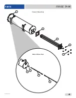
Page 52: ...45 07610 004 99 71 B RINSE TANK PARTS 1 2 3 4 5 Front of Rinse Tank 6 7 8 Back of Rinse Tank 9...

Page 53: ...4540 004 45 12 4 4 Lockwasher Split 5 16 05311 275 01 00 5 4 Nut Hex 5 16 18 05310 275 01 00 6 1 Cable Temperature Probe 05700 004 33 23 7 1 Thermistor Probe 4 with 18 Cable 06685 004 34 58 8 1 Fittin...

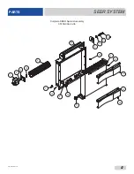
Page 54: ...47 07610 004 99 71 B SEER SYSTEM PARTS 5 4 3 14 2 6 5 1 13 7 8 11 9 12 10 12 15 16 17 18 19 Complete SEER System Assembly 05700 004 63 06...

Page 55: ...n 3 4 ID 05330 004 59 14 8 2 Bracket Enclosure Filler Plate 05700 004 58 93 9 1 Diversion Plate 05700 004 59 04 10 1 Upper Shield 05700 004 58 98 11 1 Heat Exchanger 3 8 Tubes 04420 004 58 96 12 12 Lo...

Page 56: ...49 07610 004 99 71 B TUB FRAME PARTS 7 6 2 1 13 11 10 9 12 8 DETAIL A 3 5 4 14 15 16 18 19 17...

Page 57: ...y See Door Interlock page 10 4 Foot Adjustable 05340 002 71 71 11 1 Shroud Right 05700 004 52 49 12 1 Hinge Stop Right 05700 003 32 60 13 1 1 Panel Rear Dress Edge Guard Rear Panel Not Shown 05700 004...

Page 58: ...1 Rail Left Rack 05700 031 37 88 2 1 Rail Right Rack 05700 031 37 88 3 1 Splash Shield 05700 003 33 51 4 1 Dual Float Switch 06680 004 48 53 5 1 Drain Water Tempering Kit 06401 004 59 11 Parts are not...

Page 59: ...07610 004 99 71 B 52 SCHEMATICS 208 230 V 50 60 HZ 1 PHASE...

Page 60: ...Jackson WWS Inc 6209 N US Hwy 25E Gray KY 40734 USA 1 888 800 5672 www jacksonwws com DishStar ADA SEER Manual 07610 004 99 71 B...

Reviews: