background image

16

SECTION 3:

PREVENTATIVE MAINTENANCE

Summary of Contents for Enodis 300X

Page 1: ...DOMESTIC UNITS FOR JACKSON MODELS ELECTRIC HEATED 300X 300XLT 300XN STEAM HEATED 300XS Jackson MSC Inc P O BOX 1060 HWY 25E BARBOURVILLE KY 40906 FAX 606 523 9196 PHONE 606 523 9795 www jacksonmsc com UPRIGHT DOOR DISHMACHINE SERIES July 26 2006 P N 7610 002 64 22 Revision E ...

Page 2: ......

Page 3: ...al D 02 10 2006 MAW 7205 6964 7231 7383 7553 Added 300XLT Dimensioned drawing Changed High Limit Thermostat from 05930 121 71 36 to 05930 011 49 43 Changed Rinse Thermostat from 05930 121 71 29 to 05930 510 03 79 Replace vacuum breaker 04820 300 07 00 with 04820 003 06 13 Add false panel kit assembly numbers E 07 26 2006 MAW 7571 Converted to center layout Added wash themostat kits and updat ed tu...

Page 4: ...r type dishmachine 300XLT Electrically heated low temp chemical sanitizing no rinse booster door type dishmachine 300XN Electrically heated high temp hot water sanitizing no rinse booster door type dishmachine 300XS Steam heated high temp hot water sanitizing door type dishmachine Model Serial No Installation Date Service Rep Name Phone No ...

Page 5: ...ame Assembly 38 Tub Assembly 39 Steam Tub Assembly 41 RinseTank Assembly 43 Thermostats Wash Heaters Rinse Heaters 44 Wash Pump Exploded View 45 Wash Motors 46 Water Pressure Regulator Kit WPRK Option Plumbing 47 Incoming Plumbing Assembly 47 Outlet Plumbing Assembly 49 300XN 300XS Incoming Plumbing Assembly 50 Vacuum Breaker Repair Kit 1 2 NPT 51 Solenoid Valve Repair Parts 51 300XS Incoming Stea...

Page 6: ...1 SECTION 1 SPECIFICATION INFORMATION ...

Page 7: ...m 180 F Inlet Temperature 300XN Minimum 83 C Inlet Temperature 300XLT Minimum 110 F Inlet Temperature 300XLT Minimum 44 C Gallons per Hour Approximate 52 Water Line Size 1 2 NPT Drain Line Size 1 1 2 NPT Flow Pressure PSI 20 A 5 Wash Tank Capacity Gallons 8 Wash Tank Capacity Liters 30 3 Rinse Tank Capacity Gallons 300X Only 3 Rinse Tank Capacity Gallons 300X Only 11 4 STEAM REQUIREMENTS COIL SIZE...

Page 8: ...40 3 50 N A 8 15 AMP 208 1 60 N A 26 35 AMP 230 1 60 N A 28 35 AMP 208 3 60 N A 18 25 AMP 230 3 60 N A 28 35 AMP 460 3 60 N A 8 15 AMP 300XLT RINSE TYPICAL HEATER TOTAL ELECTRICAL VOLTS PH HZ RATINGS AMPS CIRCUIT 208 1 50 N A 28 35 AMP 230 1 50 N A 30 40 AMP 208 3 50 N A 20 25 AMP 230 3 50 N A 21 30 AMP 380 3 50 N A 10 15 AMP 415 3 50 N A 10 15 AMP 440 3 50 N A 8 15 AMP 208 1 60 N A 26 35 AMP 230 ...

Page 9: ...A SECTION 1 SPECIFICATION INFORMATION 300X DIMENSIONS 4 LEGEND A Drain 1 1 2 NPT B Water Inlet 1 2 NPT C Electrical Connection NOTE All dimensions are in inches unless otherwise specified All vertical dimensions are adjustable by 1 2 1 3 cm due to the adjustable bullet feet ...

Page 10: ...300X Series Technical Manual 7610 002 64 22 Issued 07 26 2006 Revised N A SECTION 1 SPECIFICATION INFORMATION 300XN 300XLT DIMENSIONS 5 LEGEND A Drain 1 1 2 NPT B Water Inlet 1 2 NPT C Electrical Connection NOTE All dimensions are in inches unless otherwise specified All vertical dimensions are adjustable by 1 2 1 3 cm due to the adjustable bullet feet ...

Page 11: ...ATION TABLE DIMENSIONS CONNECTION TO DISHMACHINE TABLE DIMENSIONS STRAIGHT THROUGH INSTALLATION 20 1 2 52 1 cm OPENING 25 1 4 64 1 cm 2 1 2 6 4 cm 4 10 2 cm MINIMUM 2 1 2 6 4 cm 4 10 2 cm MINIMUM 20 1 2 52 1 cm OPENING 25 1 4 64 1 cm 20 1 2 52 1 cm 3 4 1 9 cm 1 1 2 3 81 cm ROLL 4 10 2 cm MINIMUM 2 1 2 6 4 cm 25 1 4 64 1 cm 20 1 2 52 1 cm OPENING 25 1 4 64 1 cm ...

Page 12: ...7 SECTION 2 INSTALLATION OPERATION INSTRUCTIONS ...

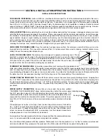
Page 13: ...cable local state and national plumbing codes The plumber is responsible for ensuring that the incoming water line is thoroughly flushed prior to connecting it to any component of the dishmachine It is necessary to remove all foreign debris from the water line that may potentially get trapped in the valves or cause an obstruction Any valves that are fouled as a result of foreign matter left in the...

Page 14: ... that you are working on the circuit The dishmachine data plate is located on the right side and to the front of the machine Refer to the data plate for machine operating requirements machine voltage total amperage load and serial number To install the incoming power lines open the control box This will require taking a phillips head screwdriver and removing the one 1 screw on the front cover of t...

Page 15: ...OW DIAGRAM 10 S WASH TANK HEATER RINSE ARM RINSE BOOSTER TANK RINSE BOOSTER HEATER Y STRAINER PRESSURE REGULATING VALVE RINSE SOLENOID VALVE VACUUM BREAKER PRESSURE GAUGE DISHMACHINE WATER TREATMENT CARTRIDGE IF INSTALLED FROM BUILDING WATER SUPPLY All items found within the dotted region are found within the footprint of the machine ...

Page 16: ...ed N A SECTION 2 INSTALLATION OPERATION INSTRUCTIONS 300XN XLT SYSTEM FLOW DIAGRAM 11 S RINSE ARM VACUUM BREAKER PRESSURE GAUGE RINSE SOLENOID VALVE WASH TANK HEATER PRESSURE REGULATING VALVE Y STRAINER WATER TREATMENT CARTRIDGE IF INSTALLED FROM BUILDING WATER SUPPLY ...

Page 17: ... SHUTOFF VALVE PRESSURE REGULATING VALVE Y STRAINER EXTERNAL STEAM BOOSTER BUILDING STEAM SUPPLY BUILDING STEAM RETURN WATER TREATMENT CARTRIDGE IF INSTALLED BUILDING WATER SUPPLY BUILDING STEAM SUPPLY BUILDING STEAM RETURN All items found within the dotted region are found within the footprint of the machine Steam plumbing should be assembled and connected to the steam booster in accordance with ...

Page 18: ... for operators Using too much detergent has as detrimental effects as using too little The proper amount of detergent must be used for job It is important to remember that certain menu items may require extra detergent by their nature and personnel need to be made aware of this Experience in using the dishmachine under a variety of conditions along with good training in the operation of the machin...

Page 19: ...hes into the machine simply defeats the purpose altogether of wash ing the ware Scraps should be removed from ware prior to being loaded into a rack Pre rinsing and pre soaking are recommended especially for silverware and casserole dishes Place cups and glasses upside down in racks so that they do not hold water during the cycle The dishmachine is meant not only to clean but to sanitize as well t...

Page 20: ...d set to the side Unscrew the wash and rinse arms from their mani folds Remove the endcaps and flush the arms with water Use a brush to clean out the inside of the arms If the nozzles appear to be clogged use a toothpick to remove the obstruction Wipe the inside of the unit out removing all soil and scraps Reassemble the wash and rinse arms and replace them in the unit The arms only need to be han...

Page 21: ...16 SECTION 3 PREVENTATIVE MAINTENANCE ...

Page 22: ...d decreases efficiency Again it is important to remind operators that trying to perform corrective maintenance on the dishmachine could lead to larg er problems or even cause harm to the operator If a problem is discovered secure the dishmachine using proper shut down procedures as listed in this manual and contact a QUALIFIED SERVICE AGENCY as listed in the back of this manual Some problems howev...

Page 23: ...18 SECTION 4 TROUBLESHOOTING ...

Page 24: ...lling 1 Wash motor faulty damaged Verify that the wash motor is getting power If so replace the motor 2 Wash motor contactor faulty Check for continuity if contacts are open replace the contactor Problem Dishmachine runs continuously in the wash cycle 1 Machine is in Delime mode Flip NORMAL DELIME switch to NORMAL mode Problem Wash or rinse heater does not work 1 Faulty heater element Check elemen...

Page 25: ...rame Adjust the frame to accommodate the doors Problem Water leaks at the wash pump 1 Wash pump seal defective Replace the seal 2 Petcock or pump drain if equipped not shut tight Close or tighten 3 Loose hoses hose clamps on the wash pump Tighten the hose clamps Problem Will not rinse during autocycle 1 Defective rinse solenoid Repair or replace the rinse solenoid as required 2 No water to the mac...

Page 26: ...21 SECTION 5 SERVICE PROCEDURES ...

Page 27: ...ED It is estimated that it will take 1 person twenty min utes to perform this task not including all of the items indicat ed in the section entitled PREPARATION IMPORTANT NOTES 1 Read these instructions thoroughly before attempt ing this maintenance evolution Become familiar with the parts and what actions need to be taken This will save time in the long run 2 The procedures demonstrated in this m...

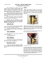
Page 28: ... coil Take the new coil and attach the conduit reinstall tighten the conduit nut and pull the wires through so that you will be able to wire the valve back up 9 Reconnect the wires from the conduit to the wires from the solenoid as they had been connected previously Ensure that the wire nuts are on tight 10 Slide the coil wire cover back on taking care not to dam age the wires 11 If you are done p...

Page 29: ...ead it is recommended that the entire valve should be replaced These instructions do not provide information on replacing the solenoid valve 16 Note Even though an O ring may not appear damaged it is a good idea to go ahead and replace it if you have a new one This will help ensure that your valve remains leak free in the future 17 Remove the diaphragm retainer and then the diaphragm itself Many p...

Page 30: ...efective replacement parts with new parts from ordered kits Ensure that components are sufficiently tightened to prevent leakage AFTER MAINTENANCE ACTIONS Reconnect the incoming water if disconnected and turn on Then restore power to the unit Run the unit for at least 10 minutes to ensure there are no leaks If any problems arise please contact Jackson SPECIAL PARTS Solenoid Valve Plunger Kit Inclu...

Page 31: ...on 1 Small flathead screwdriver 2 Needle nose pliers TIME REQUIRED It is estimated that it will take 1 person twenty min utes to perform this task not including all of the items indicat ed in the section entitled PREPARATION IMPORTANT NOTES 1 Read these instructions thoroughly before attempt ing this maintenance evolution Become familiar with the parts and what actions need to be taken This will s...

Page 32: ...a soft towel remove any grit grime or debris that may have gotten caught in the threads of both the cap retainer or the vacuum breaker body There is an O ring that should be present on the cap retainer as well Regardless of the condition of the plunger this O ring should be replaced once the cap is removed Using a small flathead screwdriver remove the old O ring 10 With the new O ring in place scr...

Page 33: ...emoved if applicable 4 Remove any and all access covers TOOLS REQUIRED The following tools may be needed to perform this maintenance evolution 1 3 8 Nutdriver 2 7 16 Combination Wrench 3 Needlenose Pliers 4 Phillipshead Screwdriver 5 Flathead Screwdriver 6 Ratchet with 1 2 Socket TIME REQUIRED It is estimated that it will take 1 person sixty minutes to perform this task not including all of the it...

Page 34: ...mounting nuts with the 3 8 nutdriver 5 Attach the jumper wires to the wires that you removed from the old thermostat Removing the imperial brass fitting Tempstar Location of the thermostat bracket JP 24 Location of the imperial brass fitting JP 24 Attaching the jumper wires Pulling the thermostat probe and fitting from the well Tempstar Removing the wires from the thermostat ...

Page 35: ...mostat so that it does not hang over the heater 9 Note regardless of the unit this is being done to the con cept is to ensure that the thermostat cannot come into contact with the heater leads or interfere with the placement of any covers 10 Use the phillipshead screwdriver to remove the attach ment screws on the thermostat for the NORMALLY CLOSED and COMMON points Tightening the brass fitting Tem...

Page 36: ... is installed it will be nece sary to ensure that it operates at the required and appropriate ranges The new thermostat has an adjustment that can be turned using a small flathead screwdriver Several cycles will need to be run on the unit while observing the final rinse tem perature The thermostat needs to cycle so that the final rinse water meets the indicated minimums on the machine data plate f...

Page 37: ...32 SECTION 6 PARTS SECTION ...

Page 38: ...300X Series Technical Manual 7610 002 64 22 Issued 07 26 2006 Revised N A SECTION 6 PARTS SECTION CONTROL BOX ASSEMBLY 33 2 28 29 9 10 11 12 14 15 30 16 13 8 1 3 4 5 6 7 26 27 17 18 19 20 21 22 23 24 25 ...

Page 39: ...2 90 19 1 Decal Control Box 09905 002 57 40 20 1 Switch Manual 05930 002 63 06 21 1 Light Blue 05945 504 05 90 22 1 Switch Cycle 05930 002 63 05 23 1 Light White 05945 504 03 90 24 1 Switch Power 05930 002 63 04 25 4 Leg Control Box 05700 002 33 05 4 Screw 1 4 20 x 2 3 4 Hex Head Cap 05305 274 13 00 4 Washer 1 4 20 ID S S 05311 174 01 00 4 Locknut 1 4 20 S S Hex with Nylon Insert 05310 374 01 00 2...

Page 40: ...Piece Weldment 05700 002 58 08 2 2 Bracket Cantilever Support 05700 031 88 00 3 6 Wear Button 50 Dia 05700 011 88 01 4 1 Clamp Double 05700 002 23 89 5 8 Bolt 1 4 20 x 1 2 S S Hex Head 05305 274 02 00 6 8 Washer 1 4 I D S S 05311 174 01 00 7 14 Locknut 1 4 20 S S Hex with Nylon Insert 05310 374 01 00 8 2 Support Hood Bolted On 05700 002 72 89 1 4 2 3 5 7 8 6 ...

Page 41: ...N CANTILEVER ARM DOOR ASSEMBLIES 36 3 5 2 1 6 9 15 16 17 18 19 11 12 20 19 11 21 22 23 18 7 8 4 24 18 14 13 10 11 12 Washer Nylon 05311 369 03 00 Yoke 05700 000 75 78 Nut 3 8 16 S S Hex Locking 05310 256 04 00 Clevis Pin 05315 700 01 00 Cotter Pin 3 32 x 3 4 05315 207 01 00 Bushing 03120 100 03 00 ...

Page 42: ...ess Steel 05311 174 01 00 12 4 Locknut 1 4 20 S S Hex with Nylon Insert Low Profile 05310 374 02 00 13 2 Sleeve Cantilever Arm 05700 000 85 69 14 2 Plug Cantilever Arm 05340 011 35 00 15 1 Magnet Reed Switch 05930 111 51 68 16 2 Locknut 8 32 S S Hex with Nylon Insert 05310 272 02 00 17 1 Door Right Side Complete Assembly 05700 002 30 88 17A 1 Right Door Weldment with Studs 05700 002 29 85 18 6 Doo...

Page 43: ...vised N A SECTION 6 PARTS SECTION FRAME ASSEMBLY 38 Front Panel 05700 002 36 65 Bolt 1 4 20 x 1 2 05305 274 02 00 Locknut 1 4 20 S S Hex with Nylon Insert 05310 374 02 00 Bullet Foot 05340 108 01 03 Frame Weldment 05700 031 48 01 Flanged Bullet Foot 05340 002 34 86 ...

Page 44: ... 6 SEE PAGE ENTITLED WASH MOTORS 32 31 22 23 21 24 25 26 27 28 29 35 36 34 33 1 30 17 16 18 19 9 20 Pump Support Bracket Complete Assembly 05700 002 00 46 Nut 1 4 20 Serrated Nut 05310 011 66 49 Bracket Motor Support Weldment 05700 002 68 31 Pump Support Adjustable Bracket 05700 002 20 41 Represents an item not shown SEE PAGE ENTITLED WASH RINSE HEATERS ...

Page 45: ...05700 001 27 55 15 1 O Ring 05330 400 05 00 16 2 Clamp Hose 1 5 16 to 2 1 4 04730 719 01 37 17 1 Discharge Hose 05700 011 88 24 18 1 Nipple 05700 021 34 84 19 1 Pump Support Bracket Assembly 05700 002 00 46 20 1 Clamp Hose 5 5 8 to 6 04730 011 34 90 21 1 Connector 1 2 90B 05975 111 01 00 22 4 Nut 3 8 16 S S Hex 05310 276 01 00 23 4 Lockwasher 3 8 05311 276 01 00 24 1 Fitting Olflex 05975 205 43 00...

Page 46: ...ies Technical Manual 7610 002 64 22 Issued 07 26 2006 Revised N A SECTION 6 PARTS SECTION STEAM TUB ASSEMBLY 41 12 10 11 2 3 25 4 7 8 13 14 11 15 5 9 3 16 6 22 23 24 21 32 26 30 27 28 24 31 1 29 17 16 18 19 20 ...

Page 47: ...0 07 13 1 Wash Overflow Weldment 05700 001 25 69 14 1 Overflow Support Bracket 05700 001 27 55 15 1 O Ring 05330 400 05 00 16 2 Clamp Hose 1 5 16 to 2 1 4 04730 719 01 37 17 1 Discharge Hose 05700 011 88 24 18 1 Nipple 05700 021 34 84 19 1 Pump Support Bracket Assembly 05700 002 00 46 20 1 Clamp Hose 5 5 8 to 6 04730 011 34 90 21 1 Connector 1 2 90B 05975 111 01 00 22 4 Nut 3 8 16 S S Hex 05310 27...

Page 48: ...93 5 1 Booster Tank Cover Weldment 05700 001 29 30 6 6 Nut Hex 5 16 18 05310 275 01 00 7 4 Locknut 1 4 20 with Nylon Insert 05310 374 01 00 8 4 Washer 1 4 ID S S Flat 05311 174 01 00 9 1 Thermostat Rinse 05930 510 03 79 1 Kit Thermostat Replacement 06401 003 13 94 The kit contains a thermostat imperial brass fitting jumper wires and instructions 10 6 Washer 5 16 I D 05311 175 01 00 11 1 Gasket Rin...

Page 49: ... 121 63 38 300X 230 50 1 04540 121 47 39 04540 121 47 40 04540 121 63 38 300X 230 50 3 04540 121 47 39 04540 121 47 40 04540 121 63 38 300X 230 60 1 04540 121 47 39 04540 121 47 40 04540 121 63 38 300X 230 60 3 04540 121 47 39 04540 121 47 40 04540 121 63 38 300X 380 50 3 04540 002 44 31 04540 002 44 32 04540 121 63 38 300X 415 50 3 04540 002 43 09 04540 002 43 10 04540 002 77 24 300X 440 50 3 045...

Page 50: ...1 2 N A 7 4 Nut Hex 3 8 16 S S N A 8 4 Cap Screw 3 8 16 x 1 1 4 S S N A 9 1 Bracket Motor to Pump N A 10 1 Slinger Pump Shaft N A 11 1 Shaft Adapter Connector N A 12 2 Allen Head Setscrew 1 4 20 x 1 4 N A 1 2 3 5 4 6 7 8 9 10 11 12 Previous models used a flat gas ket O ring seal can be replaced with flat gasket Flat gasket must be replaced with flat gasket only Apply red Loc Tite adhesive to threa...

Page 51: ...06105 121 35 18 300XN 380 50 3 06105 002 41 24 300XN 415 50 3 06105 002 41 24 300XN 440 50 3 06105 002 41 24 300XN 460 60 3 06105 121 64 21 300XLT 208 50 1 06105 002 19 87 300XLT 208 50 3 06105 002 19 87 300XLT 208 60 1 06105 121 35 18 300XLT 208 60 3 06105 121 35 18 300XLT 230 50 1 06105 002 19 87 300XLT 230 50 3 06105 002 19 87 300XLT 230 60 1 06105 121 35 18 300XLT 230 60 3 06105 121 35 18 300X...

Page 52: ...servative amounts be applied to threads when joining components together It is not advised to use thread sealing compounds sometimes referred to as pipe dope Compounds can be ejected from the threads during the tightening process and become lodged in key components thereby rendering them useless Some of the components include the solenoid valve and the pressure gauge isolation ball valve 5 3 2 1 4...

Page 53: ... NPT x 1 2 NPT x 1 4 NPT 04730 411 25 01 6 1 Valve Ball 1 4 NPT 04810 011 72 67 7 1 Gauge Pressure 0 100 PSI 06685 111 88 34 8 1 Valve Solenoid 1 2 NPT 24V 04810 100 59 00 9 1 Elbow 1 2 NPT Brass Street 04730 206 08 00 10 2 Union 1 2 NPT Brass 04730 412 05 01 11 1 Tube Copper 1 2 x 38 1 4 Long 05700 002 62 28 12 1 Elbow 1 2 90B CU to CU 04730 406 01 01 13 1 Tube Copper 1 2 x 1 3 4 Long 05700 002 6...

Page 54: ...1 59 53 3 1 Union 1 2 NPT Brass 04730 412 05 01 4 3 Plug 1 8 NPT 04730 209 07 37 5 1 Union 1 4 05700 001 16 52 6 1 Rinse Injector 05700 002 63 03 7 1 Gasket Rinse 05330 111 42 81 8 1 Tube Copper 1 2 x 32 3 4 Long 05700 002 62 29 9 3 Adapter 1 2 Male 04730 401 03 01 10 1 Elbow 1 2 NPT 90B Brass 04730 011 42 96 11 1 Tube Copper 1 2 x 2 3 4 Long 05700 002 62 29 12 1 Bushing Hex 3 4 04730 002 56 27 1 ...

Page 55: ...01 6 1 Adapter 1 2 MNPT x 1 2 FTG 04730 011 59 53 7 1 Valve Solenoid 1 2 NPT 24V 04810 100 59 00 8 1 Tee Brass 1 2 NPT x 1 2 NPT x 1 4 NPT 04730 411 25 01 9 1 Gauge Pressure 0 100 PSI 06685 111 88 34 10 1 Valve Ball 1 4 NPT 04810 011 72 67 11 1 Water Pressure Regulator 1 2 NPT 04820 100 04 07 12 2 Locknut 1 4 20 with Nylon Insert 05310 374 01 00 13 1 Bracket Plumbing Support 05700 002 64 28 14 3 P...

Page 56: ...olt Solenoid Valve Assembly 1 2 04810 100 09 18 Coil Housing only 1 2 06401 003 07 44 Screw Data Plate Coil Housing Valve Bonnet Spring Plunger Kit 06401 003 07 40 Spring position is moved for clarity Goes below the plunger O Ring Diaphragm 06401 003 07 41 Diaphragm Retainer Screen Retainer Mesh Screen Valve Body Components of Repair Kit 06401 003 06 23 Cap Screw Data Plate Cap O Ring Plunger Body...

Page 57: ...730 911 02 34 Bushing Reducing 3 4 to 1 2 04730 911 02 34 Elbow 90B 3 4 NPT Black Iron 04730 906 10 34 Union 3 4 NPT Black Iron 2 per assembly 04730 912 01 00 3 4 NPT Black Iron Pipe 05700 002 20 83 Gate Valve 3 4 NPT 04820 100 19 00 Bracket Steam Plumbing Support 05700 002 01 63 Y Strainer 3 4 NPT Black Iron 04730 217 01 32 Solenoid Valve Steam Plumbing 220V 04820 100 26 34 Nipple Close 3 4 NPT B...

Page 58: ...upport 05700 002 08 52 Coil Weldment 05700 021 41 38 Stand D Coil Support 05700 002 08 53 Stand B Coil Support 05700 002 08 51 Adapter Coil Nut 2 per assembly 05700 011 17 85 Washer Coil 2 per assembly 05700 001 17 87 Gasket Coil 4 per assembly 05700 001 17 86 Stand A Coil Support 05700 002 08 50 Complete Coil Assembly 05700 002 08 62 ...

Page 59: ...LD ASSEMBLIES 54 13 18 16 11 12 15 15 2 3 4 5 21 8 6 10 5 9 7 DETAIL B WASH ARMS MANIFOLD DETAIL A FINAL RINSE ARMS MANIFOLD 10 10 10 10 17 21 2 3 19 9 17 1 Rinse Injector Weldment 1 per machine 05700 002 63 03 Rinse Injector Gasket 2 per machine 05330 111 42 81 Plug 1 8 NPT Brass 3 per Rinse Injector 04730 209 07 37 14 ...

Page 60: ...01 00 2 Rinse Arm Assembly 05700 002 58 09 11 1 Clip Retaining Rinse Head Bushing 05340 112 01 11 12 2 Rinse Arm Washer 05330 011 42 10 13 1 Bushing Rinse Head 05700 021 33 84 14 1 Rinse Arm 05700 031 49 58 15 2 Plug Rinse Arm S S 04730 609 04 00 16 1 Bearing Rinse 03120 002 72 24 17 2 Bearing Assembly 05700 021 35 97 17a 1 Hub Nut 05700 011 35 94 17b 1 Hub Bushing 05700 011 35 96 17c 1 Hub Spindl...

Page 61: ...R INTERLOCK SDI OPTION 56 Safety Door Interlock Box Bottom 05700 001 21 26 Safety Door Interlock Box Cover 05700 001 21 27 Other Safety Door Interlock SDI components not shown Pipe Clamp found on the side of the machine 05700 000 35 05 Solenoid Electrical Interlock Option 04810 100 61 33 Relay 05945 111 47 51 ...

Page 62: ...eries Technical Manual 7610 002 64 22 Issued 07 26 2006 Revised N A SECTION 6 PARTS SECTION EXHAUST FAN CONTROL OPTION 57 Delay Timer 05945 011 65 44 2 Din Rail 05700 002 36 09 Terminal Board 05940 011 84 41 ...

Page 63: ...of the hood 6 Holes in false panel willl ine up with rack assembly holes 7 Re install screws for rack assembly which will secure false panel to unit 8 Re assemble the rack track in an L shape for a corner opera tion Bottom of side panel Insert this side first False panel positioned in unit Rack rail removed reposi tioned for a corner operation Left Front False Panel Weldment 05700 002 75 52 Right ...

Page 64: ...mpression Fitting as required Attach to the incoming cold water line Use pipe dope or thread tape as required to prevent any leaks Thermostat 05930 003 13 65 Solenoid Valve 04810 100 09 18 To Cold Water Supply Nipple Close 1 2 NPT Not Shown 04730 207 15 00 Valve Check 1 2 Not Shown 04820 002 55 77 Lid Drain Quench 05700 002 67 16 Box Drain Quench 05700 002 69 96 Reducer 1 1 2 to 1 2 04730 002 55 7...

Page 65: ...60 SECTION 7 ELECTRICAL SCHEMATICS ...

Page 66: ...300X Series Technical Manual 7610 002 64 22 Issued 07 26 2006 Revised N A SECTION 7 ELECTRICAL SCHEMATICS 300X 300XN 300XLT 208 230 VOLT 50 60 HERTZ SINGLE THREE PHASE 61 ...

Page 67: ...300X Series Technical Manual 7610 002 64 22 Issued 07 26 2006 Revised N A SECTION 7 ELECTRICAL SCHEMATICS 300X 300XN 300XLT 380 440 460 VOLT 50 60 HERTZ THREE PHASE 62 ...

Page 68: ...300X Series Technical Manual 7610 002 64 22 Issued 07 26 2006 Revised N A SECTION 7 ELECTRICAL SCHEMATICS 300X 300XN 300XLT 415 VOLT 50 60 HERTZ THREE PHASE 63 ...

Page 69: ...300X Series Technical Manual 7610 002 64 22 Issued 07 26 2006 Revised N A SECTION 7 ELECTRICAL SCHEMATICS 300X 300XN 300XLT 208 230 380 460 VOLT 50 60 HERTZ SINGLE THREE PHASE 64 ...

Reviews: