background image

VISUAL INSPECTION:

Before installing the unit, check the container

and machine for damage. A damaged container is an indicator that
there may be some damage to the machine. If there is damage to both
the container and machine, do not throw away the container. The dish-
machine has been inspected and packed at the factory and is expect-
ed to arrive to you in new, undamaged condition. However, rough han-
dling by carriers or others may result in there being damage to the unit
while in transit. If such a situation occurs, do not return the unit to
Jackson; instead, contact the carrier and ask them to send a repre-
sentative to the site to inspect the damage to the unit and to complete
an inspection report. You must contact the carrier within 48 hours of
receiving the machine. Also, contact the dealer through which you pur-
chased the unit.

UNPACKING THE DISHMACHINE:

Once the machine has been

removed from the container, ensure that there are no missing parts
from the machine. This may not be obvious at first. If it is discovered
that an item is missing, contact Jackson immediately to have the miss-
ing item shipped to you. 

LEVEL THE DISHMACHINE:

The dishmachine is designed to oper-

ate while being level. This is important to prevent any damage to the
machine during operation and to ensure the best results when wash-
ing ware. The unit comes with adjustable bullet feet, which can be
turned using a pair of channel locks or by hand if the unit can be
raised safely. Ensure that the unit is level from side to side and from
front to back before making any connections.

PLUMBING THE DISHMACHINE:

All plumbing connections must

comply with all applicable local, state, and national plumbing codes.
The plumber is responsible for ensuring that the incoming water line
is thoroughly flushed prior to connecting it to any component of the
dishmachine. It is necessary to remove all foreign debris from the
water line that may potentially get trapped in the valves or cause an
obstruction. Any valves that are fouled as a result of foreign matter left
in the water line, and  any expenses resulting from this fouling, are not
the responsibility of the manufacturer.

CONNECTING THE DRAIN LINE:

The JPX-140 model covered in

this manual has a gravity discharge drain. Remove the drain plug from
the tub and the unit will drain itself. The unit comes with a flexible drain
hose that should be connected to the drain. The drain hose connec-
tion must drain downward and away from the machine. 

The drain for the JPX-160 & JPX-200, is a pumped discharge drain.
Both of these dishmachines must be drained into a stand pipe (like a
household washing machine). If  they are not, they will siphon them-
selves empty. The stand pipe for the JPX-160 is between 20 and 24
inches tall. The stand pipe for the JPX-200 is between 24 and 28 inch-
es tall. All piping from the machine to the drain must be a minimum 1”
I.P.S. and shall not be reduced. 

There must also be an air gap between the machine drain line and the
floor sink or drain. If a grease trap is required by code, it should have
a flow capacity of 5 gallons per minute.

PRIMING THE DRAIN LINE: 

For the JPX-160 and JPX-200 models,

prime the drain pump before use when the machine is full of water.
Lower the end of the drain hose and allow some water to drain from
the hose. Raise the end of the hose and connect it to its installation
position.

WATER SUPPLY CONNECTION: 

Ensure that you have read the sec-

tion entitled “PLUMBING THE DISHMACHINE” above before pro-
ceeding. Install the water supply line (1/2” pipe size minimum) to the
to the vacuum breaker on the back of the machine. For ease of ser-

vice, the final water line connection to the machine should be using a
length of flexible hose, suitable for the pressure and temperature of
the incoming water. It is recommended that a water shut-off valve be
installed in the water line between the main supply and the machine
to allow access for service. 

The water supply line is to be capable of 20 

A

5 PSI “flow” pressure

at the recommended temperature indicated on the data plate. 

In areas where the water pressure fluctuates or is greater than the
recommended pressure, it is suggested that a water pressure regula-
tor be installed. The JPX series units do not come with water pressure
regulators as standard equipment.

Do not confuse static pressure with flow pressure. Static pressure is
the line pressure in a “no flow” condition (all valves and services are
closed). Flow pressure is the pressure in the fill line when the fill valve
is opened during the cycle.

It is also recommended that a shock absorber (not supplied with the
JPX series units) be installed in the incoming water line. This prevents
line hammer (hydraulic shock), induced by the solenoid valve as it
operates, from causing damage to the equipment.

PLUMBING CHECK:

Slowly turn on the water supply to the machine

after the incoming fill line and the drain line have been installed.
Check for any leaks and repair as required. All leaks must be repaired
prior to placing the machine in operation.

ELECTRICAL POWER CONNECTION:

Electrical and grounding con-

nections must comply with the applicable portions of the National
Electrical Code ANSI/NFPA 70 (latest edition) and/or other electrical
codes.

Disconnect electrical power supply and place a tag at the disconnect
switch to indicate that you are working on the circuit.

Refer to the data plate for machine operating requirements,
machine voltage, total amperage load and serial number.

To install the incoming power lines for the JPX-140, route the power
lines through the grommet located in the rear  AT THE TOP OF THE
MACHINE.

WARNING: do not attempt to route incoming power lines
to the dispenser terminal block located at the bottom of

the JPX-140! Contact your authorized Jackson service agency or
Jackson technical service if there are any questions.

To install the incoming power lines for the JPX-160 & JPX-200  route
the power lines through the grommet located at the rear of the
machine towards the bottom. Install the service wires (L1, L2 &
Ground) to the appropriate terminals on the terminal block. It is rec-
ommended that “DE-OX” or another similar anti-oxidation agent be
used on all power connections.

VOLTAGE CHECK:

Ensure that the power switch is in the OFF posi-

tion and apply power to the dishmachine. Check the incoming power
at the terminal block and ensure it corresponds to the voltage listed on
the data plate. If not, contact a qualified service agency to examine
the problem. Do not run the dishmachine if the voltage is too high or
too low. Shut off the service breaker and mark it as being for the dish-
machine. Advise all proper personnel of any problems and of the loca-
tion of the service breaker. Replace the control box cover and tighten
down the screws. 

INSTALLATION INSTRUCTIONS

1

I

N

S
T

R
U
C

T

I

O
N

S

Summary of Contents for Hot Water Sanitizing Undercounter Dishmachines JPX-160

Page 1: ...X 140 JPX 160 JPX 200 Jackson MSC Inc P O BOX 1060 HWY 25E BARBOURVILLE KY 40906 FAX 606 523 9196 PHONE 606 523 9795 www jacksonmsc com An Company HOT WATER SANITIZING UNDERCOUNTER DISHMACHINES April 30 2004 P N 7610 002 68 17 Revision E ...

Page 2: ...This page intentionally left blank ...

Page 3: ...tions of the JPX 160 21 Dimensions JPX 160 22 JPX 160 Front View 23 Electrical Panel 24 Front and Bottom View 25 Rear View 27 Wash Arm Rinse Arm Assemblies 28 Inside Tub View 30 Miscellaneous 31 Electrical Diagram 208 240 Volt 60 Hertz 1 Phase 32 Electrical Diagram 12 Volt Circuit 33 JPX 160 Components Diagram 34 V JPX 200 Specifications of the JPX 200 35 Dimensions JPX 200 36 Main Assembly 37 Ele...

Page 4: ...e end of the hose and connect it to its installation position WATER SUPPLY CONNECTION Ensure that you have read the sec tion entitled PLUMBING THE DISHMACHINE above before pro ceeding Install the water supply line 1 2 pipe size minimum to the to the vacuum breaker on the back of the machine For ease of ser vice the final water line connection to the machine should be using a length of flexible hos...

Page 5: ...iner has been allowed to empty the system may be primed as follows a Ensure a cycle is not in progress b Press and hold the drain switch until rinse prime appears in the display c On models with drain pump the message draining will appear first The message rinse prime will appear after a fur ther few seconds DO NOT release the switch when the draining message is showing as this will start a drain ...

Page 6: ...o scroll between menu options and variable values TO ENTER ENGINEERING MODE 1 Turn machine off wait until the display is blank 2 Open the door and hold a pencil or similar item against the door switch shaft 3 Switch on and as soon as the display appears press the door switch shaft 5 times within 4 seconds 4 The display should change to rinse overlap thus showing you are in the Engineering Mode Scr...

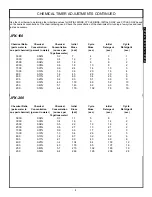
Page 7: ... 0 5 14 8 6 2 2000 0 05 0 6 18 10 8 2 1500 0 07 0 9 24 14 10 3 1000 0 10 1 3 36 20 16 4 800 0 13 1 6 45 26 20 5 600 0 17 2 1 60 34 26 6 400 0 25 3 2 90 51 39 9 300 0 33 4 3 119 68 52 13 250 0 40 5 1 143 82 63 15 200 0 50 6 4 179 102 78 19 I N S T R U C T I O N S JPX 200 Chemical Ratio Chemical Chemical Initial Cycle Initial Cycle parts water to Concentration Concentration Rinse Rinse Detergent Det...

Page 8: ...y all of the bacteria that could be harmful to human beings In order to do this ware must be properly prepared prior to being placed in the machine DAILY MACHINE PREPARATION Refer to the section entitled PREPARATION at the top of this page and follow the instructions there Afterwards check that all of the chemical levels are correct and or that there is plenty of detergent available for the expect...

Page 9: ...the event this reflector is removed to be cleaned make sure it is reattached with the lip facing downward away from the top of the unit as shown in the picture below Remove the rear left and right strainer supports and clean as required Remove the wash and drain strainers and clean them as required Wipe out the entire tub Use a damp cloth to clean the tank never use abrasive material such as steel...

Page 10: ...ing output signal is on For use only in the engineering programming mode only Green LED Display Contrast Adjuster Turn clockwise to adjust the brightness of the display It will not unscrew When it reach es the brightest spot it will restart at the dimmest setting I N S T R U C T I O N S ...

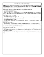
Page 11: ...aler to fit a boost er pump to increase pressure 3 Check that the rinse jets are not blocked by limescale or solid wastes 4 Check if water hoses are trapped or kinked 5 Check if the bushing at the center of the wash rinse arm assemblies are loose or missing this allows dirt into the rinse jets which may be blocked Problem Water marks on glasses 1 Use correct chemicals which do not produce foam and...

Page 12: ...se numbers are provided in this manual simply for reference and may change without notice at any given time RINSE TYPICAL HEATER TOTAL ELECTRICAL VOLTS PH HZ RATINGS AMPS CIRCUIT 208 1 60 2 7 KW 208V 24 30 AMP 230 1 60 3 3 KW 230V 26 35 AMP WATER REQUIREMENTS INLET TEMPERATURE 140 F WATER LINE SIZE I P S Minimum 1 2 DRAIN LINE SIZE I D Minimum 1 FLOW PRESSURE P S I 20 A5 GALLONS PER RACK 49 GALLON...

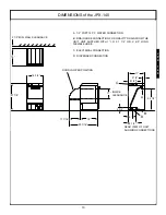
Page 13: ... FOR GRAVITY DRAIN FROM THE UNIT UNIT SUPPLIED WITH 1 I D X 1 1 2 O D X 6 0 LONG FLEXIBLE HOSE C ELECTRICAL CONNECTION D DISPENSER CONNECTION 18 27 7 8 11 7 16 29 7 16 18 4 2 3 4 8 1 2 11 INSIDE CLEARANCE REAR VIEW OF UNIT SHOWING CONNECTIONS 16 3 4 17 2 1 2 8 1 2 22 1 2 C A B D DOOR IN OPEN POSITION J P X 1 4 0 ...

Page 14: ... 2020 142 27 18 05 1 Metal Facia Plate for Switches 2020 142 67 95 06 1 Black Plastic Top Panel 2020 142 27 34 07 1 Wash Gauge 2020 142 67 97 08 1 Handle 2020 162 27 73 09 1 Door 2020 142 27 50 10 1 Rinse Gauge 2020 142 67 96 11 1 Lower Front Panel 2020 142 27 53 12 1 Rinse Gauge 2020 162 27 60 FRONT ASSEMBLY 11 02 03 05 04 06 01 08 09 10 1 11 07 12 J P X 1 4 0 ...

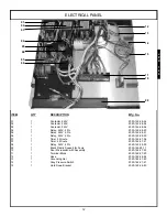
Page 15: ...mer 2 Minute 2020 142 27 06 07 1 Timer 4 Minute 2020 142 37 21 08 1 Relay 240V 4 Pin 2020 142 28 50 09 1 Black Plastic Support for Facia 2020 162 28 11 10 1 Door Microswitch with Assembly 2020 162 27 23 11 1 Terminal Block 2020 162 27 20 12 1 Hose 2020 162 28 24 13 1 Grounding Nut 2020 162 27 60 14 1 Gray Pressure Switch 2020 162 27 21 15 1 Hold Down Bracket 2020 162 26 80 ELECTRICAL PANEL 12 01 0...

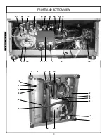
Page 16: ...FRONT AND BOTTOM VIEW 13 02 03 01 04 05 06 07 08 09 10 12 13 14 11 15 16 17 18 19 11 21 20 22 23 25 06 26 19 24 09 28 24 27 24 01 07 09 10 J P X 1 4 0 ...

Page 17: ...162 27 43 12 3 Hex Nut 2020 162 27 93 13 1 Heater Gasket 2020 142 27 92 14 1 Rinse Heater Element 2020 142 28 49 15 1 Thermostat 2020 142 26 98 16 1 Support Bracket 2020 142 67 99 17 1 Thermostat 2020 142 26 98 18 1 Base Cover 2020 142 27 51 19 1 Terminal Block 2020 142 68 00 20 1 Washer Fiber 2020 162 28 05 21 1 Bolt Drain 2020 162 28 04 22 2 Screw 2020 162 27 98 23 2 Nut 2020 162 27 93 24 3 Hose...

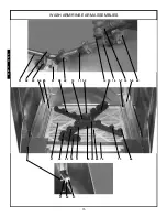
Page 18: ...WASH ARM RINSE ARM ASSEMBLIES 15 01 02 03 04 07 08 09 29 30 31 10 26 25 24 14 13 06 21 22 23 28 27 05 11 12 15 16 17 18 19 20 14 J P X 1 4 0 ...

Page 19: ... 1 Support Front Filter 2020 162 28 21 15 2 Wash Arm 2020 162 26 75 16 2 Rinse Jet Support 2020 142 26 44 17 1 Support Right Hand Filter 2020 142 27 56 18 1 Door Switch Assembly 2020 142 68 05 19 1 Ramp Right Hand Basket 2020 162 28 10 20 2 Rinse Halo Endcap 2020 142 68 00 21 2 Pin Hinge 2020 162 28 07 22 2 C Clip Hinge Pin 2020 162 27 38 23 2 Spacer Hinge Pin 2020 162 27 39 24 1 Flange Bottom 202...

Page 20: ... Filter 2020 142 27 87 07 1 Tube Transfer 2020 142 26 51 08 1 Air Bell Assembly 2020 162 26 97 09 1 Hold Down Bracket 2020 142 68 07 10 1 Body Wash Filter 2020 162 27 86 11 1 Element Wash with Washer and Nuts 2020 162 27 04 12 1 Waste Boss 2020 162 26 94 13 1 O Ring 2020 162 27 62 14 1 Nut Filter 2020 162 27 82 INSIDE TUB VIEW 17 09 11 02 04 01 05 14 07 08 03 12 13 10 06 14 Represents an item not ...

Page 21: ...ater Inlet Hose 2020 162 27 84 04 1 Hose 4 6 mm 2020 142 68 82 05 1 Drain Elbow 2020 142 26 96 06 1 Gray Drain Hose 2020 162 28 57 07 1 Waste Hose 2020 142 68 83 08 1 Vacuum Breaker 2020 142 68 84 09 1 Tee 2020 142 68 85 10 1 Bracket 2020 142 68 80 REAR VIEW 18 01 03 04 01 02 05 06 07 08 09 10 J P X 1 4 0 ...

Page 22: ... 1 Cover Rinse Element 2020 142 27 99 05 1 Plate Rack 2020 142 68 11 06 1 Dish Rack 2020 142 68 12 07 1 Catch Ball Assembly 2020 162 27 31 08 1 Switch Micro Door Assembly 2020 162 27 23 09 2 External Corner Piece 2020 162 27 33 10 2 Internal Corner Piece 2020 162 27 32 MISCELLANEOUS 19 01 02 03 04 08 09 09 05 06 07 J P X 1 4 0 ...

Page 23: ...JPX 140 ELECTRICAL DIAGRAM 208 240 VOLT 60 HERTZ 1 PHASE 20 J P X 1 4 0 ...

Page 24: ...s manual simply for reference and may change without notice at any given time RINSE TYPICAL HEATER TOTAL ELECTRICAL VOLTS PH HZ RATINGS AMPS CIRCUIT 208 1 60 2 7 KW 208V 24 30 AMP 230 1 60 3 3 KW 230V 26 35 AMP WATER REQUIREMENTS INLET TEMPERATURE 140 F GALLONS PER RACK 59 GALLONS PER HOUR 14 2 WATER LINE SIZE I P S Minimum 1 2 DRAIN LINE SIZE I D 1 FLOW PRESSURE P S I 20 A5 FRAME DIMENSIONS WIDTH...

Page 25: ...N FOR PUMPED DRAIN FROM THE UNIT DISCHARGE HEIGHT MUST BE MAINTAINED UNIT SUP PLIED WITH 1 I D X 1 1 2 O D X 6 0 LONG FLEXIBLE HOSE C ELECTRICAL CONNECTION 20 29 5 8 13 7 16 33 7 16 20 5 1 4 2 3 4 5 14 INSIDE CLEARANCE REAR VIEW OF UNIT SHOWING CONNECTIONS 19 19 2 1 2 24 B A C DOOR IN OPEN POSITION J P X 1 6 0 ...

Page 26: ...itch 2020 162 27 14 05 1 Metal Facia Panel for Switches 2020 162 28 12 06 1 Digital Display 2020 162 28 55 07 1 Top Black Panel 2020 162 28 08 08 4 Foot for Machine 2020 162 27 43 09 1 Gauge 2020 162 28 75 10 1 Front Panel 2020 162 28 17 11 1 Door 2020 162 28 14 JPX 160 FRONT VIEW 23 10 09 08 11 02 01 03 04 06 01 07 05 01 J P X 1 6 0 ...

Page 27: ...oor Microswitch with Assembly 2020 162 27 23 07 1 Top Panel 2020 162 28 08 08 1 Gray Pressure Switch 2020 162 27 21 09 1 Thermal Circuit Breaker 4 Amp 2020 162 68 91 10 1 Hose Rinse 2020 162 28 24 11 1 Hose Clamp 2020 162 27 60 12 1 Thermal Circuit Breaker 4 Amp 2020 162 68 91 13 1 Gasket 2020 162 26 80 14 1 Outlet Pipe 2020 162 26 79 ELECTRICAL PANEL 24 01 02 03 04 05 06 07 08 09 10 11 12 13 14 J...

Page 28: ...FRONT AND BOTTOM VIEW 25 02 03 04 01 05 06 07 08 09 10 11 12 13 14 15 16 17 20 11 25 24 10 26 28 30 29 27 22 08 10 10 19 18 05 01 21 06 23 23 J P X 1 6 0 ...

Page 29: ...lement Securing 2020 162 27 93 14 1 Heater Rinse 2020 142 28 49 15 1 Gasket Heater Element 2020 142 27 92 16 1 Pump Head Rinse Agent 2020 162 28 31 17 1 Bracket Soap Pump 2020 162 27 75 18 1 Outlet Pipe 2020 162 26 79 19 1 Hose Rinse 2020 162 28 24 20 1 Pump Head Soap 2020 162 28 30 21 1 Hose Rinse 2020 162 28 24 22 1 Solenoid Valve 12 Volts 2020 162 27 03 23 2 Motor Soap Rinse Aid Pump 2020 162 2...

Page 30: ...IPTION Mfg No 01 1 Water Inlet Hose 2020 162 27 84 02 1 Drain Hose 2020 162 28 57 03 1 Back Panel 2020 162 28 13 04 1 Solenoid 2020 162 27 03 05 1 Vacuum Breaker 2020 142 68 84 REAR VIEW 27 05 04 03 01 02 J P X 1 6 0 ...

Page 31: ...WASH ARM RINSE ARM ASSEMBLIES 28 01 02 03 04 19 20 21 22 23 24 17 16 15 06 14 18 11 12 13 05 07 08 10 09 J P X 1 6 0 ...

Page 32: ...embly 2020 162 27 35 11 2 Pin Hinge 2020 162 28 07 12 2 C Clip Hinge Pin 2020 162 27 38 13 2 Spacer Hinge Pin 2020 162 27 39 14 1 Ramp Left Hand Basket 2020 162 28 09 15 1 Filter Plastic 2020 162 28 18 16 1 Flange Bottom 2020 162 26 42 17 12 Jet Rinse 2020 162 26 57 18 1 Support Front Filter 2020 162 28 21 19 1 Plug Drain 2020 162 26 92 20 1 Center Boss 2020 202 26 39 21 4 O Ring Rinse Arm 2020 16...

Page 33: ... 08 1 Elbow Assembly 2020 162 26 46 09 1 O Ring 2020 162 27 83 10 2 Nut 1 Plastic 2020 142 27 64 11 1 Right Filter Support 2020 162 28 20 12 1 Left Filter Support 2020 162 28 19 13 1 Element Wash 2020 162 27 04 14 1 Waste Boss 2020 162 26 94 15 1 O Ring 2020 162 27 61 16 1 Nut Filter 2020 162 27 82 17 1 Wash Filter Body 2020 162 27 86 18 1 Wash Filter Base 2020 162 27 87 INSIDE TUB VIEW 30 12 13 0...

Page 34: ...External 2020 162 27 33 06 2 Corner Piece Internal 2020 162 27 32 07 1 Dish Rack 2020 162 68 14 08 1 Plate Rack 2020 162 68 15 09 1 Terminal Block 2020 162 27 20 10 2 Contactor 240 Volt 3NO 1NC 2020 142 28 54 11 2 Contactor 12 Volt Coil B6C 2020 162 28 53 12 1 Contactor Safety 240 Volt 2020 162 68 16 MISCELLANEOUS 31 01 02 10 10 11 11 Front View 12 Bottom Right Side View 11 09 07 08 03 04 05 06 J ...

Page 35: ...JPX 160 ELECTRICAL DIAGRAM 208 240 VOLT 60 HERTZ 1 PHASE 32 J P X 1 6 0 ...

Page 36: ...JPX 160 ELECTRICAL DIAGRAM 12 VOLT CIRCUIT 33 J P X 1 6 0 ...

Page 37: ...JPX 160 COMPONENTS DIAGRAM 34 J P X 1 6 0 ...

Page 38: ... These numbers are provided in this manual simply for reference and may change without notice at any given time RINSE TYPICAL HEATER TOTAL ELECTRICAL VOLTS PH HZ RATINGS AMPS CIRCUIT 208 1 60 6 KW 208V 45 60 AMP 230 1 60 7 3 KW 230V 48 60 AMP WATER REQUIREMENTS INLET TEMPERATURE 140 F GALLONS PER RACK 98 GALLONS PER HOUR 23 5 WATER LINE SIZE I P S Minimum 1 2 DRAIN LINE SIZE I D 1 FLOW PRESSURE P ...

Page 39: ... PUMPED DRAIN FROM THE UNIT DISCHARGE HEIGHT MUST BE MAINTAINED UNIT SUP PLIED WITH 1 I D X 1 1 2 O D X 6 0 LONG FLEXIBLE HOSE C ELECTRICAL CONNECTION 23 3 4 32 1 4 14 3 8 38 1 8 23 3 4 2 3 4 6 3 4 14 INSIDE CLEARANCE REAR VIEW OF UNIT SHOWING CONNECTIONS 23 23 1 4 5 1 2 5 28 B A D DOOR IN OPEN POSITION J P X 2 0 0 ...

Page 40: ...020 202 27 15 05 1 Drain Switch 2020 162 27 14 06 1 Visual Display 2020 162 28 55 07 1 Metal Facia for Switches 2020 202 26 27 08 1 Door Handle 2020 162 27 73 09 1 Pressure Gauge 2020 162 28 75 10 1 Door 2020 202 26 90 11 4 Foot 2020 162 27 43 12 1 Front Bottom Panel 2020 202 26 31 MAIN ASSEMBLY 37 01 06 02 03 04 05 07 08 10 09 12 11 J P X 2 0 0 ...

Page 41: ...8 76 06 2 Switches 2020 162 68 91 07 1 PCB Support Bracket 2020 202 69 10 08 1 Bracket 2020 202 69 09 09 1 Black Plastic Support for Facia 2020 202 26 26 10 1 Outlet Pipe 2020 202 26 89 11 1 Hose Clamp 2020 162 27 62 12 1 Top Boss 2020 162 26 78 13 1 PCB 2020 162 28 74 14 1 Gasket 2020 162 26 80 15 1 Door Microswitch Assembly 2020 162 27 23 ELECTRICAL PANEL 38 01 02 03 04 05 14 06 08 09 10 11 12 1...

Page 42: ...FRONT AND BOTTOM VIEW 39 15 10 11 12 13 09 14 16 17 21 22 23 05 05 08 28 29 25 27 07 25 19 26 08 24 25 08 18 04 20 20 01 02 03 04 05 06 07 08 J P X 2 0 0 ...

Page 43: ...ket 2020 202 28 67 13 3 Nut Hex 2020 162 27 93 14 1 Pump Head Rinsing Agent 2020 162 28 31 15 1 Bracket Soap Pump 2020 162 27 75 16 1 Pump Head Soap 2020 162 28 30 17 4 Foot Machine 2020 162 27 43 18 1 Cover Rinse Heater 2020 162 28 00 19 1 Outlet Pipe 2020 202 26 89 20 2 Motor Pump Head 2020 162 28 33 21 1 Washer Fiber 2020 162 28 05 22 1 Bolt Drain 2020 162 28 04 23 1 Pump Drain 2020 162 28 56 2...

Page 44: ... 84 03 1 Back Panel 2020 202 26 28 04 1 Solenoid Valve 12V Double Water 2020 202 37 20 05 1 Conduit Connector Fitting 2020 202 69 07 06 1 Vacuum Breaker 2020 142 68 84 07 1 Tee 2020 142 68 85 08 1 Tee 2020 202 69 08 09 1 Hose 2020 162 27 84 REAR VIEW 41 06 04 03 02 05 07 08 09 01 J P X 2 0 0 ...

Page 45: ...02 26 25 09 4 Wash Jet L H S 2020 162 26 65 10 4 Wash Jet R H D 2020 162 26 54 11 8 Wash Jet Nut 2020 162 26 63 12 2 Wash Jet Blank 2020 162 26 64 13 2 Wash Arm 2020 202 26 86 14 1 Bottom Flange 2020 162 26 42 15 1 Center Boss 2020 202 26 39 16 2 Rinse Arm O Ring 2020 162 26 60 17 2 Rinse Jet Blank 2020 162 26 58 18 2 Rinse Arm 2020 202 26 87 19 6 Rinse Jet Nut 2020 162 26 56 20 6 Rinse Jet 2020 1...

Page 46: ...020 202 26 85 07 1 Elbow Assembly 2020 202 26 47 08 1 O Ring 2020 162 27 83 09 1 Nut 1 Plastic 2020 142 27 64 10 1 Support Right Filter 2020 162 28 20 11 1 Support Left Filter 2020 162 28 19 12 2 Filter Nut 2020 162 27 82 13 1 Support Front Filter 2020 202 26 35 14 1 Wash Element with Washers and Nuts 2020 202 28 39 INSIDE TUB VIEW 43 12 11 13 14 01 02 04 05 06 07 08 09 10 03 12 13 05 04 12 Indica...

Page 47: ...05 2 External Corner Piece 2020 162 27 33 06 2 Internal Corner Piece 2020 162 27 32 07 1 Silverware Strainer Basket 2020 202 68 26 08 1 Contactor 240V 2020 142 28 54 09 1 Terminal Block 2020 202 27 19 10 1 Contactor 240V 2020 142 28 54 11 1 Contactor 12V 2020 162 28 53 12 1 Contactor 12V Wash Heater Relay 2020 162 28 52 MISCELLANEOUS 44 01 02 09 10 08 11 12 03 04 05 06 07 J P X 2 0 0 ...

Page 48: ...JPX 200 ELECTRICAL DIAGRAM 208 230 VOLT 60 HERTZ 1 PHASE 45 J P X 2 0 0 ...

Page 49: ...JPX 200 ELECTRICAL DIAGRAM 12 VOLT CIRCUIT 46 J P X 2 0 0 ...

Page 50: ...JPX 200 COMPONENTS DIAGRAM 47 J P X 2 0 0 ...

Page 51: ......

Reviews: