background image

2

JP-24BPNSU Technical Manual

7610-002-38-50 Rev. D (11/11/2005)

SECTION 1: SPECIFICATION INFORMATION

SPECIFICATIONS

PERFORMANCE/CAPABILITIES

OPERATING CAPACITY 

(RACKS/HOUR)

RACKS PER HOUR                               

21

DISHES PER HOUR                               

525

GLASSES PER HOUR                            

525

OPERATING CYCLE 

(SECONDS)

WASH TIME

120

RINSE TIME

15

TOTAL CYCLE TIME

150

TANK CAPACITY 

(GALLONS)

WASH TANK                                          

5.65

RINSE TANK                                          

3

WASH PUMP CAPACITY

GALLONS PER MINUTE                         

60

TEMPERATURES

WASH---°F (MINIMUM)                                   

150

RINSE---°F                                                      

180-195

ELECTRICAL REQUIREMENTS

WASH PUMP MOTOR HORSEPOWER

3/4

WATER REQUIREMENTS

INLET TEMPERATURE

140°F

GALLONS PER HOUR

52.3

WATER LINE SIZE I.P.S. (MINIMUM)

1/2”

DRAIN LINE SIZE I.P.S. (MINIMUM)

1 1/2”

FLOW PRESSURE P.S.I.

20 

A

5

FLOW, GALLONS PER MINUTE

7.1

FRAME DIMENSIONS

WIDTH

24 1/4”

DEPTH

22 5/8”

HEIGHT,  MINIMUM

33 1/4”

HEIGHT, MAXIMUM

34 1/4”

MAXIMUM INSIDE CLEARANCE HEIGHT

14 1/2”

CLEARANCE, WALL TO MACHINE

2 1/2”

NOTE: Always refer to the machine data plate for specific
electrical and water requirements. The material provided on
this page is for reference only and may be subject to change
without notice.

VOLTS HERTZ PHASE

HEATER 

RATINGS

HEATER 

AMPS

MOTOR 

AMPS

TOTAL 

AMPS

460

60

3

480/8.2KW

9.4

1.6

11

460

60

3

480/10KW

12

1.6

13.6

Summary of Contents for JP-24BPNSU

Page 1: ...TION INSTALLATION AND MAINTENANCE INSTRUCTIONS Jackson MSC Inc P O BOX 1060 HWY 25E BARBOURVILLE KY 40906 PHONE 606 523 9795 FAX 606 523 9196 www jacksonmsc com An Company HOT WATER SANITIZING UNDERCOUNTER DISHMACHINE November 11 2005 P N 7610 002 38 50 Revision D ...

Page 2: ... attempted repair by unau thorized persons improper installation if serial number has been removed or altered or if unit is used for purpose other than it was origi nally intended TRAVEL LIMITATIONS Jackson MSC limits warranty travel time to 2 two hours and mileage to 100 one hundred miles Jackson MSC will not pay for travel time and mileage that exceeds this or any fees such as those for air or b...

Page 3: ...ed 2nd Enodis logo to cover D 11 11 05 MAW 6964 6988 7006 7383 Changed thermostat from 05930 121 71 36 to 05930 011 49 43 Added 4 3 4 Din Rail 05700 002 90 18 to Control Box Assembly Changed thermostat bracket from 05700 011 73 72 to 05700 011 81 64 Changed vacuum breaker from 04820 300 07 00 to 04820 003 06 13 Added service procedure pages Changed to new layout Updated schematic i ...

Page 4: ...allation Date Service Rep Name Phone No JP 24BPNSU Technical Manual 7610 002 38 50 Rev D 11 11 2005 NOMENCLATURE FOR THE MODEL COVERED IN THIS MANUAL JP 24BPNSU JP 24BPNSU Hot water sanitizing electrically heated dishmachine ...

Page 5: ...CONTRACT NO NSN NO OF UNITS CID APL DLA 400 90 M 1376 7320 01 144 2638 1 432100007 REMARKS DATE CERTIFICATION IT IS HEREBY CERTIFIED THAT THE TECHNICAL MANUAL PROVIDED UNDER CONTRACT NUMBER DLA 400 90 M 1376 FOR DISHWASHING MACHINE MODEL JP 24BPNSU HAS BEEN APPROVED BY THE APPROVAL DATA SHOWN ABOVE TITLE OF COMPANY OFFICIAL COMPANY S NAME COMPANY S ADDRESS COMPANY S FSCM JP 24BPNSU Technical Manua...

Page 6: ...CHANGE RECORD JP 24BPNSU Technical Manual 7610 002 38 50 Rev D 11 11 2005 ii Change No Date Title Brief Description Signature of Validating Officer ...

Page 7: ...avy use MANUFACTURER Jackson MSC Inc Barbourville Kentucky 40906 PURCHASE ORDER OR CONTRACT NO DLA 400 90 M 1376 EQUIPMENT Dishmachine Model JP 24BPNSU ADDITIONAL IDENTIFICATION if any Not applicable DATE 1 January 1991 2 ADDITIONAL COPIES Additional copies are available from DGSG SDA Richmond Virginia 23297 JP 24BPNSU Technical Manual 7610 002 38 50 Rev D 11 11 2005 iii ...

Page 8: ...Breaker Repair Parts Kit 20 Replacing the Pump Motor Replacing the Heater 22 Replacing Drain Valve 23 VI PARTS SECTION Electrical Panel Assembly 25 Gauge Panel Assembly 26 Kick Plate Assembly 27 Incoming Plumbing Assembly 28 Solenoid Valve Vacuum Breaker Repair Kits 31 Drain Valve Assembly 32 Drain Plumbing Assembly 33 Wash Motor to Wash Tub Assembly 34 Wash Motor Assembly 35 Rinse Tank Components...

Page 9: ...1 SECTION 1 SPECIFICATION INFORMATION ...

Page 10: ...HORSEPOWER 3 4 WATER REQUIREMENTS INLET TEMPERATURE 140 F GALLONS PER HOUR 52 3 WATER LINE SIZE I P S MINIMUM 1 2 DRAIN LINE SIZE I P S MINIMUM 1 1 2 FLOW PRESSURE P S I 20 A5 FLOW GALLONS PER MINUTE 7 1 FRAME DIMENSIONS WIDTH 24 1 4 DEPTH 22 5 8 HEIGHT MINIMUM 33 1 4 HEIGHT MAXIMUM 34 1 4 MAXIMUM INSIDE CLEARANCE HEIGHT 14 1 2 CLEARANCE WALL TO MACHINE 2 1 2 NOTE Always refer to the machine data ...

Page 11: ... 14 1 2 Height maximum 34 1 4 Inside Clearance Width 20 1 4 Width 24 1 4 Inside Clearance Depth 21 1 4 Depth 22 5 8 Door Open Depth 39 1 2 Wall Clearance minimum 2 1 2 Legend A Drain Connection flexible hose 6 0 free length 1 ID x 1 3 8 OD B Electrical Connection C Water Inlet 1 2 Female Pipe Thread 2 1 2 AFF D Detergent Feeder Connection MIN WALL CLEARANCE D A B C C 33 3 4 16 3 4 22 5 8 2 1 2 19 ...

Page 12: ...4 SECTION 2 INSTALLATION OPERATION INSTRUCTIONS ...

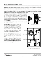
Page 13: ...om the water line that may potential ly get trapped in the valves or cause an obstruction Any valves that are fouled as a result of foreign matter left in the water line and any expenses resulting from this fouling are not the responsibility of the manufacturer CONNECTING THE DRAIN LINE The drain for the JP 24BPNSU is a pumped pressure drain capable of pumping waste water to a height of 24 inches ...

Page 14: ... to see if they will come loose It is recommended that DE OX or another similar anti oxidation agent be used on all power connections VOLTAGE CHECK Ensure that the power switch is in the OFF position and apply power to the dishmachine Check the incoming power at the terminal block and ensure it cor responds to the voltage listed on the data plate If not con tact a qualified service agency to exami...

Page 15: ...ow at the location where the dishmachine will be permanently positioned Install 3 8 stainless steel lug bolts to secure tracks and caps to the deck Drill holes into deck as shown below and insure rear holes are located 2 1 4 from the wall The racks and rear end caps may be tightened at this time Slide dishmachine onto tracks and into position at rear end caps Install front end caps into place and ...

Page 16: ...cialist and detergent vendor and come up with a complete training program for operators Using too much detergent has as detrimental effects as using too little The proper amount of detergent must be used for job It is important to remember that certain menu items may require extra detergent by their nature and personnel need to be made aware of this Experience in using the dishmachine under a vari...

Page 17: ...acteria that could be harmful to human beings In order to do this ware must be properly prepared prior to being placed in the machine DAILY MACHINE PREPARATION Refer to the section entitled PREPARATION at the top of this page and follow the instruc tions there Afterwards check that all of the chemical levels are correct and or that there is plenty of detergent available for the expected workload W...

Page 18: ...10 SECTION 3 PREVENTATIVE MAINTENANCE ...

Page 19: ...to remind operators that trying to perform corrective maintenance on the dishmachine could lead to larg er problems or even cause harm to the operator If a problem is discovered secure the dishmachine using proper shut down procedures as listed in this manual and contact Jackson Some problems however may having nothing to do with the machine itself and no amount of preventative maintanence is goin...

Page 20: ...12 SECTION 4 TROUBLESHOOTING ...

Page 21: ...t in manual wash switch Replace switch Problem No water comes through the rinse arms when the ON FILL switch is depressed 1 Water not turned on Turn water on 2 Defective solenoid valve Replace solenoid valve 3 Probes are dirty or coated Clean probes 4 Defective water level control Replace Problem Little or no water coming through the rinse assemblies 1 Limed up rinse heads or piping Delime rinse h...

Page 22: ...hine doesn t drain when OFF DRAIN switch is pressed 1 Drain solenoid clogged Remove obstruction 2 Defective OFF DRAIN switch Replace 3 Defective motor or motor start relay Replace 4 Defective drain solenoid Replace 5 Defective timer Replace Problem No indication of pressure 1 Water turned off Turn water on 2 1 4 test cock ball valve is closed Open the ball valve JP 24BPNSU Technical Manual 7610 00...

Page 23: ...15 SECTION 5 SERVICE PROCEDURES ...

Page 24: ...s estimated that it will take 1 person twenty min utes to perform this task not including all of the items indicat ed in the section entitled PREPARATION IMPORTANT NOTES 1 Read these instructions thoroughly before attempt ing this maintenance evolution Become familiar with the parts and what actions need to be taken This will save time in the long run 2 The procedures demonstrated in this manual a...

Page 25: ...ke the new coil and attach the conduit reinstall tighten the conduit nut and pull the wires through so that you will be able to wire the valve back up 9 Reconnect the wires from the conduit to the wires from the solenoid as they had been connected previously Ensure that the wire nuts are on tight 10 Slide the coil wire cover back on taking care not to dam age the wires 11 If you are done performin...

Page 26: ...is recommended that the entire valve should be replaced These instructions do not provide information on replacing the solenoid valve 16 Note Even though an O ring may not appear damaged it is a good idea to go ahead and replace it if you have a new one This will help ensure that your valve remains leak free in the future 17 Remove the diaphragm retainer and then the diaphragm itself Many problems...

Page 27: ...ersing the steps needed to take it apart Replace defective replacement parts with new parts from ordered kits Ensure that components are sufficiently tightened to prevent leakage AFTER MAINTENANCE ACTIONS Reconnect the incoming water if disconnected and turn on Then restore power to the unit Run the unit for at least 10 minutes to ensure there are no leaks If any problems arise please contact Jack...

Page 28: ...ad screwdriver 2 Needle nose pliers TIME REQUIRED It is estimated that it will take 1 person twenty min utes to perform this task not including all of the items indicat ed in the section entitled PREPARATION IMPORTANT NOTES 1 Read these instructions thoroughly before attempt ing this maintenance evolution Become familiar with the parts and what actions need to be taken This will save time in the l...

Page 29: ... examine it With a soft towel remove any grit grime or debris that may have gotten caught in the threads of both the cap retainer or the vacuum breaker body There is an O ring that should be present on the cap retainer as well Regardless of the condition of the plunger this O ring should be replaced once the cap is removed Using a small flathead screwdriver remove the old O ring 10 With the new O ...

Page 30: ... wire leads from the motor wiring box 11 Install replacement motor in reverse order of above REPLACING THE BOOSTER TANK HEATER The following list of tools will be needed to complete this procedure phillips screwdriver and 1 2 socket and ratchet 1 Disconnect the electrical power to the dishwasher at the main circuit breaker box when servicing Place a tag on the cir cuit box indicating the circuit i...

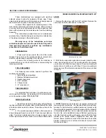
Page 31: ...Siphon out the water or remove inlet hose to drain valve and drain into pan The dishmachine may be drained by opening the petcock on the pump housing or by removing the wash thermometer bulb from the lower wash tank 7 Use a 5 16 nutdriver to loosen the hose clamp and remove the inlet hose to the drain valve from the pump motor 8 Use a phillips screwdriver to remove the cover from the valve Use a f...

Page 32: ...24 SECTION 6 PARTS SECTION ...

Page 33: ...700 031 62 94 10 1 Grommet 1 1 8 Heyco 05975210 08 00 11 1 Wire Lug 05940 200 76 00 12 1 Ground Decal 09905 011 41 82 13 1 Overload Contactor 05945111 60 08 14 1 ACME Transformer 480 to 120 Volt 05950 011 50 70 15 1 Terminal Board 1 4 QC 05940 021 94 85 16 2 Screw 6 32 x 3 8 Sems with External Tooth Lockwasher 05305 002 25 91 17 1 Locknut 10 24 S S Hex with Nylon Insert 05310 373 01 00 18 1 Timer ...

Page 34: ... Decal Control Panel 09905 031 40 55 7 1 Thermometer 96 Wash 06685 111 68 49 8 1 Thermometer 48 Rinse 06685 111 68 48 9 1 Switch ON FILL OFF DRAIN 05930 301 49 55 10 1 Light Red 05945111 44 45 11 1 Switch Delime 05930 011 49 00 12 1 Light Amber 05945111 44 44 13 1 Light Green 05945111 44 43 14 1 Breaker 2A Circuit 05925 111 64 18 15 1 Light Red 05945111 44 45 JP 24BPNSU Technical Manual 7610 002 3...

Page 35: ...NSU Technical Manual 7610 002 38 50 Rev D 11 11 2005 Kickplate Weldment 05700 041 86 40 Control Panel Only 09330 041 85 00 Nut Nylon Wing 1 4 20 05310 994 01 00 Dielectric Cover Kickplate Panel 05700 011 40 49 Decal Power Disconnect Warning 09905 021 47 07 ...

Page 36: ... x 1 2 x 1 4 04730 411 25 01 4 1 Ball Valve Test Cock 1 4 04810 011 72 67 5 1 Valve Solenoid 1 2 110 volt 04810 100 12 18 6 1 Union 1 2 C to C 04730 412 05 01 7 2 Elbow 1 2 C to Ftg 04730 406 31 01 8 1 Copper Tube 1 2 x 18 1 2 05700 011 44 34 9 1 Elbow 1 2 90 Deg C to MSPS 04730 406 32 01 JP 24BPNSU Technical Manual 7610 002 38 50 Rev D 11 11 2005 1 7 2 6 3 2 5 2 4 8 7 9 ...

Page 37: ...Ftg x Male 04730 401 03 01 Plug 1 4 Brass 3 per machine 04730 209 01 00 Injector Weldment 05700 031 41 83 Adapter 1 2 Ftg x Male 04730 401 03 01 Copper Tube 1 2 x 20 1 4 05700 031 41 83 Elbow 1 2 NPT 90B Brass 04730 011 42 96 Nipple 1 2 Close Brass 04730 207 15 00 Pipe Clamp 05700 011 38 62 Secure with Locknut 1 4 20 S S Hex with Nylon Insert 05310 374 01 00 ...

Page 38: ...2005 Rinse Stiffener Weldment 05700 002 59 79 Locknut 1 4 20 S S Hex with Nylon Insert 05310 374 01 00 Gasket Rinse 05330 111 42 81 Gasket Rinse 05330 111 42 81 Rinse Hub Weldment 05700 021 38 31 Locknut 1 4 20 S S Hex with Nylon Insert 05310 374 01 00 Hose 3 4 x 8 1 2 05700 011 38 83 Clamp Hose 04730 719 06 09 ...

Page 39: ...ousing 06401 003 07 43 Valve Bonnet Spring Plunger Kit 06401 003 07 40 Diaphragm Retainer Screen Retainer Mesh Screen Valve Body Complete 110 Volt Solenoid Valve Assembly 04810 100 12 18 Complete Vacuum Breaker Assembly 04820 003 06 13 Components of Repair Kit 06401 003 06 23 Cap Screw Data Plate Cap O Ring Plunger Body Cap Retainer Diaphragm O ring Kit 06401 003 07 41 ...

Page 40: ... 02 5 4 Tricnut 10 32 AK Fastener S S 05340 111 58 10 6 1 Lockwasher 10 External Tooth 05311 273 02 00 7 1 Grommet Heyco 05975210 03 00 8 1 Cam Weldment 05700 011 65 78 9 1 Plate Dielectric 05700 011 65 80 10 1 Switch Micro 05930 011 65 81 11 2 Screw 4 40 x 5 8 05305 011 49 70 12 1 Motor Chemical Feeder Pump 14 RPM 220 Volt 04320 011 79 34 13 1 Terminal Ground Spade 05940 011 75 70 14 4 Locknut 10...

Page 41: ...verter Valve Assembly 06401 022 23 21 5 1 Clamp 11 16 to 1 1 4 04730 002 18 40 6 1 Hose 1 I D x 10 Feet Long 05700 011 39 72 7 2 Locknut 1 4 20 S S Hex with Nylon Insert 05310 374 01 00 8 2 Bolt 1 4 20 x 1 2 Long 05305 274 02 00 9 1 Bracket Valve Mounting with Tricnuts 05700 021 66 37 10 2 Washer 10 External Tooth Star 05311 273 02 00 JP 24BPNSU Technical Manual 7610 002 38 50 Rev D 11 11 2005 1 2...

Page 42: ...0 5 1 Hose 1 1 4 x 2 1 4 Reinforced 05700 011 44 48 6 1 Motor Wash 06105 121 60 06 7 1 Hose Bottom Manifold Pump 05700 001 22 92 8 1 Gasket Suction Adapter 05330 021 40 87 9 1 Casting Suction Adapter 09515 031 39 86 10 4 Washer S S 1 4 20 I D 05311 174 01 00 11 6 Locknut 1 4 20 S S 05310 374 01 00 12 4 Washer 1 4 I D x 3 4 O D S S 05311 011 76 30 JP 24BPNSU Technical Manual 7610 002 38 50 Rev D 11...

Page 43: ...nical Manual 7610 002 38 50 Rev D 11 11 2005 Pump Casing Only 05930 021 44 07 Wash Pump Impeller 04320 021 44 02 Mechanical Seal 05330 011 44 06 Wash Pump Gasket 05330 011 44 08 Test Cock Motor Only 06105 002 64 03 Complete Assembly 460 Volt 3 4 Hp 06105 121 60 06 ...

Page 44: ...h Washer 05305 002 25 91 Rinse Tank Weldment 05700 031 38 09 Secured with Locknut 1 4 20 S S Hex with Nylon Insert 05310 374 01 00 Dielectric Cover 05700 011 40 50 Gasket Heater 05330 011 47 79 Fitting 1 4 Imperial Brass 05310 924 02 05 Nut 5 16 18 S S Hex 05310 275 01 00 Lockwasher 5 16 Split 05311 275 01 00 The JP 24BNSU comes supplied with various heaters depending on the characteristics of the...

Page 45: ...bly 05700 011 44 37 10 1 Baffle Door 05700 001 44 75 11 1 Seal Channel Inner Door Right 05700 031 32 91 12 1 Latch Assembly 05700 011 44 41 13 1 Inner Door 05700 031 32 85 14 1 Seal Channel Inner Door Top 05700 031 32 90 15 12 Fastener Screw 10 32 Counter Sink 1 2 Long 05305 011 44 51 16 1 Striker Door Switch 05700 011 44 24 17 2 Fastener Screw 10 32 x 1 2 Long 05305 011 44 52 18 2 Locknut 10 32 S...

Page 46: ...g 05700 011 44 40 Latch Roller 05700 011 44 38 Latch Spring 05700 011 44 39 Door Latch Assembly 05700 011 44 41 Stop Left Hinge 05700 021 37 67 Cover Left Hinge Weldment 05700 002 18 41 Stop Right Hinge 05700 021 37 68 Cover Right Hinge Weldment 05700 002 18 42 Switch Plate 05700 011 44 22 Door Switch 05930 303 38 00 Hinge Components secured with Locknut 1 4 20 S S Hex with Nylon Insert 05310 374 ...

Page 47: ...30 011 42 10 Rinse Arm 05700 031 38 30 Plug Rinse Arm 04730 609 04 00 Bushing Rinse Head 05700 021 33 84 Bearing Rinse Head 03120 002 72 24 Ring Retaining 05340 112 01 11 Wash Arm Weldment 05700 021 46 58 Bearing Assembly 05700 021 35 97 O ring Not Shown 05330 002 60 69 Wash Arm Assembly 05700 021 39 23 Rinse Arm Assembly 05700 031 39 21 ...

Page 48: ... Technical Manual 7610 002 38 50 Rev D 11 11 2005 Guide Right Rack 05700 031 37 88 Guide Left Rack 05700 031 37 89 Back Panel 05700 031 44 33 Strainer Spacer 05700 021 35 83 Attaches with Nut Nylon Wing 1 4 20 05310 994 01 00 Strainer Weldment 05700 031 35 81 ...

Page 49: ...ght Frame Weldment 05700 011 73 86 The swivel feet used on the unit may be ordered using 05340 108 02 00 Shroud Weldment 05700 031 38 15 Secured with 10 32 x 1 2 Long Screws 05305 173 04 00 Right Dress Panel 05700 041 38 08 Left Dress Panel 05700 041 38 37 Top Panel 05700 041 38 38 The Panels are secured with 10 32 x 1 2 Truss Head Screws 05305 011 39 36 ...

Page 50: ...SECTION 7 ELECTRICAL DIAGRAMS 42 ...

Page 51: ...43 SECTION 7 ELECTRICAL DIAGRAMS JP 24BPNSU 460 VOLT 60 HERTZ THREE PHASE JP 24BPNSU Technical Manual 7610 002 38 50 Rev D 11 11 2005 9905 031 51 11 ...

Page 52: ...10H FOR MAILING CLASSIFIED TMDERS 3 Submit TMDERS at web site http nsdsa nswses navy milor mail 1 PUB NO 2 VOL PART 3 REV NO DATE OR TM CH NO DATE 4 SYSTEM EQUIPMENT IDENTIFICATION 5 TITLE 6 REPORT CONTROL NUMBER UIC YEAR XXXX 7 RECOMMENDED CHANGES TO PUBLICATION PAGE NO A PARA GRAPH B C RECOMMENDED CHANGES AND REASONS 8 ORIGINATOR S NAME AND WORK CENTER Please Print 9 DATE 10 DSN COMM NO 11 TRANS...

Page 53: ...45 FOLD HERE FOLD HERE DEPARTMENT OF THE NAVY PLACE POSTAGE HERE COMMANDER NSDSA CODE 5E30 NAVSURFWARCENDIV 4363 MISSILE WAY PORT HUENEME CA 93043 4307 ...

Page 54: ...10H FOR MAILING CLASSIFIED TMDERS 3 Submit TMDERS at web site http nsdsa nswses navy milor mail 1 PUB NO 2 VOL PART 3 REV NO DATE OR TM CH NO DATE 4 SYSTEM EQUIPMENT IDENTIFICATION 5 TITLE 6 REPORT CONTROL NUMBER UIC YEAR XXXX 7 RECOMMENDED CHANGES TO PUBLICATION PAGE NO A PARA GRAPH B C RECOMMENDED CHANGES AND REASONS 8 ORIGINATOR S NAME AND WORK CENTER Please Print 9 DATE 10 DSN COMM NO 11 TRANS...

Page 55: ...47 FOLD HERE FOLD HERE DEPARTMENT OF THE NAVY PLACE POSTAGE HERE COMMANDER NSDSA CODE 5E30 NAVSURFWARCENDIV 4363 MISSILE WAY PORT HUENEME CA 93043 4307 ...

Page 56: ...SECTION 8 JACKSON MAINTENANCE REPAIR CENTERS 48 ...

Page 57: ...800 424 1414 FAX 650 635 1919 pndappl aol com GCS SERVICE INC 650 S GRAND AVE 111 SANTA ANA CA 92705 714 541 8496 800 327 1433 COLORADO HAWKINS COMMERCIAL APPLIANCE SERVICE 56 BUCHANAN COLORADO SPRINGS CO 80110 719 477 1242 FAX 719 477 1513 HAWKINS COMMERCIAL APPLIANCE SERVICE 3000 S WYANDOT ST ENGLEWOOD CO 80110 303 781 5548 800 624 2117 FAX 303 761 8861 METRO APPLIANCE SERVICE 1640 S BROADWAY DE...

Page 58: ...10 FAX 317 549 6286 GENERAL PARTS INC 622 LA PAS TRAIL INDIANAPOLIS IN 46268 317 290 8060 800 410 9794 FAX 317 290 8085 IOWA GOODWIN TUCKER GROUP 3509 DELAWARE AVENUE DES MOINES IA 50313 515 262 9308 800 372 6066 FAX 515 262 2936 goodwintuc aol com GOODWIN TUCKER GROUP 958 W PARKER ST WATERLOO IA 50703 319 232 5049 800 554 5049 FAX 319 232 2247 GOODWIN TUCKER GROUP 935 33RD AVE SW CEDAR RAPIDS IA ...

Page 59: ...OUTH KINGSHIGHWAY ST LOUIS MO 63110 314 535 2222 FAX 314 535 6205 petek kps stl com GENERAL PARTS INC 1101 EAST 13TH ST KANSAS CITY MO 64106 816 421 5400 800 279 9967 FAX 816 421 1270 MONTANA RESTAURANT APPLIANCE SVC 7219 ROOSEVELT WAY NE SEATTLE WA 98115 206 524 8200 800 433 9390 FAX 206 525 2890 info restappl com NEBRASKA GOODWIN TUCKER GROUP 7535 D STREET OMAHA NE 68124 402 397 2880 800 228 037...

Page 60: ...HERWEE DRIVE RALEIGH NC 27603 919 779 2266 FAX 919 779 2224 info whaleyfoodservice com WHALEY FOODSERVICE REPAIRS 6418 101 AMSTERDAM WAY WILMINGTON NC 28405 910 791 0000 FAX 910 791 6662 info whaleyfoodservice com NORTH DAKOTA GCS SERVICE INC 2857 LOUISIANA AVENUE N MINNEAPOLIS MN 55427 612 546 4221 800 345 4221 FAX 612 546 4286 GENERAL PARTS INC 10 SOUTH 18TH STREET FARGO ND 58103 701 235 4161 80...

Page 61: ...com SOUTH DAKOTA GENERAL PARTS INC 10 SOUTH 18TH STREET FARGO ND 58103 701 235 4161 800 279 9987 FAX 701 235 0539 TENNESSEE GCS SERVICE INC 3717 CHERRY ROAD MEMPHIS TN 38118 901 366 4587 800 262 9155 FAX 901 366 4588 TENNESSEE cont GCS SERVICE INC 748 FESSLERS LANE NASHVILLE TN 37210 615 244 8050 800 831 7174 FAX 615 244 8885 TEXAS GCS SERVICE INC AUSTIN TX 800 822 2303 ARMSTRONG REPAIR CENTER 170...

Page 62: ...ELLOIT RD WEST ALLIS WI 53219 414 543 6460 800 236 6460 FAX 414 543 6480 ascmil execpc com APPLIANCE SERVICE CENTER 786 MORRIS AVE GREEN BAY WI 54304 920 496 9993 800 236 0871 FAX 920 496 9927 ascfox execpc com METROPOLITAN SERVICE 3210 LONDON RD EAU CLAIRE WI 54701 715 832 0555 800 848 3945 FAX 715 832 7813 GENERAL PARTS SERVICE W223 N735 SARATOGA DR WAUKESHA WI 53186 262 650 6666 800 279 9976 FA...

Page 63: ......
Reviews: