41
SECTION 6: PARTS SECTION
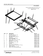
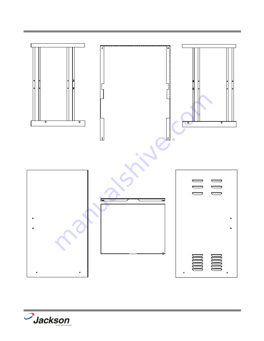
FRAME, SHROUD, & PANEL COMPONENTS
JP-24BPNSU Technical Manual
7610-002-38-50 Rev. D (11/11/2005)
Left Frame Weldment
05700-011-73-85
Right Frame Weldment
05700-011-73-86
The swivel feet used on the unit may be ordered using 05340-108-02-00
Shroud Weldment
05700-031-38-15
Secured with 10-32 x 1/2” Long Screws
05305-173-04-00
Right Dress Panel
05700-041-38-08
Left Dress Panel
05700-041-38-37
Top Panel
05700-041-38-38
The Panels are secured with 10-32 x 1/2” Truss Head Screws, 05305-011-39-36
Summary of Contents for JP-24BPNSU
Page 9: ...1 SECTION 1 SPECIFICATION INFORMATION ...
Page 12: ...4 SECTION 2 INSTALLATION OPERATION INSTRUCTIONS ...
Page 18: ...10 SECTION 3 PREVENTATIVE MAINTENANCE ...
Page 20: ...12 SECTION 4 TROUBLESHOOTING ...
Page 23: ...15 SECTION 5 SERVICE PROCEDURES ...
Page 32: ...24 SECTION 6 PARTS SECTION ...
Page 50: ...SECTION 7 ELECTRICAL DIAGRAMS 42 ...
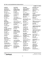
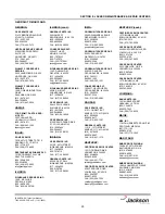
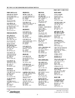
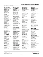
Page 56: ...SECTION 8 JACKSON MAINTENANCE REPAIR CENTERS 48 ...
Page 63: ......


