background image

JPX-300 Installation/Operation Manual 7610-002-71-26 Rev. J

Issued: 03-09-2006  Revised: 09-14-2006

SECTION 2: INSTALLATION/OPERATION INSTRUCTIONS

8

INSTALLATION INSTRUCTIONS

VISUAL INSPECTION:

Before installing the unit, check the container and machine for damage. A damaged container is an indi-

cator that there may be some damage to the machine. If there is damage to both the container and machine, do not throw away
the container. The dishmachine has been inspected and packed at the factory and is expected to arrive to you in new, undam-
aged condition. However, rough handling by carriers or others may result in there being damage to the unit while in transit. If
such a situation occurs, do not return the unit to Jackson; instead, contact the carrier and ask them to send a representative to
the site to inspect the damage to the unit and to complete an inspection report. You must contact the carrier within 48 hours of
receiving the machine. Also, contact the dealer through which you purchased the unit.

UNPACKING THE DISHMACHINE:

Once the machine has been removed from the container, ensure that there are no miss-

ing parts from the machine. This may not be obvious at first. If it is discovered that an item is missing, contact Jackson imme-
diately to have the missing item shipped to you. 

LEVEL THE DISHMACHINE:

The dishmachine is designed to operate while being level.

This is important to prevent any damage to the machine during operation and to ensure the
best results when washing ware. The unit comes with adjustable bullet feet, which can be
turned using a pair of channel locks or by hand if the unit can be raised safely. Ensure that
the unit is level from side to side and from front to back before making any connections.

PLUMBING THE DISHMACHINE:

All plumbing connections must comply with all applica-

ble local, state, and national plumbing codes. The plumber is responsible for ensuring that
the incoming water line is thoroughly flushed prior to connecting it to any component of the
dishmachine. It is necessary to remove all foreign debris from the water line that may poten-
tially get trapped in the valves or cause an obstruction. Any valves that are fouled as a result
of foreign matter left in the water line, and  any expenses resulting from this fouling, are not
the responsibility of the manufacturer. A water hardness test must be performed to deter-
mine if the HTS-11 (scale prevention and corrosion control) need to be installed. A hardness
test kit is attached to the warning tag that is attached to the y-strainer toward the front of the
machine. If the hardness is higher than 5 GPG the HTS-11 will need to be installed, please
contact Jackson immediately to have this item shipped to you.

WATER SUPPLY CONNECTION FOR MACHINES WITH A WATER HARDNESS
GREATER THAN 5 GPG: 

Ensure that you have read the section entitled “PLUMBING THE

DISHMACHINE” above before proceeding. Install the HTS-11 into the water line (1/2” ID
pipe size minimum) before the dishmachine line y-strainer using copper pipe. The HTS-11
must be installed vertically. A mounting bracket is provided to facilitate the venture metering
head to the wall. Observe proper inlet/outlet water directions. Flow directions are molded
into the top of the head. It is recommended that a water shut-off valve be installed before
the HTS-1 to allow access for servicing. Plumb from the HTS-11 outlet to the y-strainer using
copper pipe (or order the 1/2” ID flexible hose kit offered by Jackson). The water supply line
is to be capable of 20

±

5 PSI “flow” pressure at the recommended temperature indicated on

the data plate. See “Pressure Regulator” and “Shock Absorber” sections.

WATER SUPPLY CONNECTION FOR MACHINES WITH A WATER HARDNESS OF 5
GPG OR LESS:

Ensure that you have read the section entitled “PLUMBING THE DISHMA-

CHINE” above before proceeding. Install the water supply line (1/2” ID pipe size minimum)
to the dishmachine line y-strainer using copper pipe (or order the 1/2” ID flexible hose kit
offered by Jackson). It is recommended that a water shut-off valve be installed in the water
line between the main supply and the machine to allow access for service. The water sup-
ply line is to be capable of 20

±

5 PSI “flow” pressure at the recommended temperature indi-

cated on the data plate. 

PRESSURE REGULATOR: 

Do to areas where the water pressure fluctuates or is greater

than the recommended pressure, it is recommended installing a water pressure regulator. Do not confuse static pressure with
flow pressure. Static pressure is the line pressure in a “no flow” condition (all valves and services are closed). Flow pressure
is the pressure in the fill line when the fill valve is opened during the cycle.

Adjustable Bullet Foot

Incoming Plumbing Y-Strainer

Back of Machine Showing Drain Hose

Drain Hose

Summary of Contents for JPX-300H

Page 1: ...S JPX 300H JPX 300HC JPX 300HN JPX 300L Jackson MSC Inc P O BOX 1060 HWY 25E BARBOURVILLE KY 40906 PHONE 606 523 9795 FAX 606 523 9196 www jacksonmsc com An Company JPX 300 UNDERCOUNTER DISHMACHINE SERIES March 06 2007 P N 7610 002 71 26 Revision J ...

Page 2: ...on if serial number has been removed or altered or if unit is used for purpose other than it was origi nally intended TRAVEL LIMITATIONS Jackson MSC limits warranty travel time to 2 two hours and mileage to 100 one hundred miles Jackson MSC will not pay for travel time and mileage that exceeds this or any fees such as those for air or boat travel without prior authorization WARRANTY REGISTRATION C...

Page 3: ... PRODUCT FAILURE TO DO SO WILL VOID THE WARRANTY LLAME AL 1 888 800 5672 PARA REGISTRAR ESTE PRODUCTO AL NO HACERLO LA GARANTIA SERA ANULADA S V P APPELER 1 888 800 5672 POUR ENREGISTRER CE PRODUIT LA GARANTIE SERA ANNULEE POUR TOUT PRODUIT NON ENREGISTREE ...

Page 4: ...ematics for use with stainless steel switches Changed JPX 300LP to JPX 300L G 11 15 05 MAW 7552 Add instructions and schematics for use with the univeral timers H 01 30 06 MAW 7602 Update schematics with universal timers 9905 003 12 88 9905 002 12 84 9905 003 13 84 9905 003 13 86 to match relay to contactor change I 02 07 06 MAW 7602 Update Schematic 09905 002 72 28 with relay to contactor change ...

Page 5: ...Name Phone No Jackson MSC Inc provides technical support for all of the dishmachines detailed in this manual We strongly recommend that you refer to this manual before making a call to our technical support staff Please have this manual with you when you call so that our staff can refer you if necessary to the prop er page Technical support is available from 8 00 a m to 5 00 p m EST Monday through...

Page 6: ...hes 208 240 V 60 HZ single phase 22 JPX 300H JPX 300HN S S Switches Contactor 208 240 V 60 HZ single phase 23 JPX 300H JPX 300HN Univeral Timer SS Switches 208 240 V 60 HZ single phase 24 JPX 300H JPX 300HN 460 V 60 HZ three phase 25 JPX 300H JPX 300HN Stainless Steel Switches 460 V 60 HZ three phase 26 JPX 300H JPX 300HN Univeral Timer SS Switches 460 V 60 HZ three phase 27 JPX 300H JPX 300HN Ext...

Page 7: ...1 SECTION 1 SPECIFICATION INFORMATION ...

Page 8: ...ne and 2 typical fixed trip cir cuit breaker sizes as listed in the NEC 2002 Edition Local codes may require more stringent protection than what is dis played here Always verify with your electrical service con tractor that your circuit protection is adequate and meets all applicable national and local codes These numbers are pro vided in this manual simply for reference and may change without not...

Page 9: ...PM 50 ELECTRICAL REQUIREMENTS WASH MOTOR HP 3 4 NOTE Typical Electrical Circuit is based upon 1 125 of the full amperage load of the machine and 2 typical fixed trip cir cuit breaker sizes as listed in the NEC 2002 Edition Local codes may require more stringent protection than what is dis played here Always verify with your electrical service con tractor that your circuit protection is adequate an...

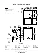
Page 10: ... cm Depth 22 5 8 57 5 cm Door Open Depth 39 1 2 100 3 cm Wall Clearance minimum 2 1 2 6 4 cm All dimensions are for reference only and are subject to change without notice LEGEND A Water Inlet 1 2 Female Pipe Thread 2 1 2 AFF B Chemical Feeder Connection C Electrical Connection D Rinse Additive Connection E Drain Connection Flexible Hose 6 Free Length 1 ID x 1 3 8 OD 12 30 5 cm 19 48 3 cm 24 60 9 ...

Page 11: ...4 84 5 cm Inside Clearance Height 14 1 2 36 8 cm Height maximum 34 1 4 87 cm Inside Clearance Width 20 1 4 51 4 cm Width 24 60 9 cm Inside Clearance Depth 21 1 4 54 cm Depth 22 5 8 57 5 cm Door Open Depth 39 1 2 100 3 cm Wall Clearance minimum 2 1 2 6 4 cm All dimensions are for reference only and are subject to change without notice A A C E C D E B 24 60 9 cm 22 5 8 57 5 cm 16 3 4 42 5 cm DOOR OP...

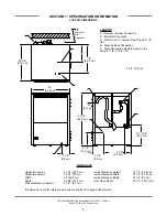
Page 12: ...se Additive Connection E Drain Connection Flexible Hose 6 Free Length 1 ID x 1 3 8 OD DIMENSIONS Height minimum 33 1 4 84 5 cm Inside Clearance Height 14 1 2 36 8 cm Height maximum 34 1 4 87 cm Inside Clearance Width 20 1 4 51 4 cm Width 24 60 9 cm Inside Clearance Depth 21 1 4 54 cm Depth 22 5 8 57 5 cm Door Open Depth 39 1 2 100 3 cm Wall Clearance minimum 2 1 2 6 4 cm All dimensions are for ref...

Page 13: ...7 SECTION 2 INSTALLATION OPERATION INSTRUCTIONS ...

Page 14: ... the responsibility of the manufacturer A water hardness test must be performed to deter mine if the HTS 11 scale prevention and corrosion control need to be installed A hardness test kit is attached to the warning tag that is attached to the y strainer toward the front of the machine If the hardness is higher than 5 GPG the HTS 11 will need to be installed please contact Jackson immediately to ha...

Page 15: ...el open the door slightly while carefully lifting the kick panel up and out of the way Install 3 4 conduit into the pre punched holes in the back of the control box Route power wires and connect to power block and ground ing lug Install the service wires L1 and L2 to the appropriate terminals as they are marked on the terminal block Install the grounding wire into the lug provided It is recommende...

Page 16: ...mp and wash tank prior to the dispensing of chemicals Sanitizer in concentration is caustic and may cause damage without dilution 1 Verify that the proper chemical tube stiffener inlet is in the proper container 2 Use the prime switches located at the top of the unit to prime each pump The switches are clearly marked D R and S as to what chemical feeder pump they are assigned to 3 To prime the pum...

Page 17: ...e option time is in seconds In the time categories each second in use will light up To deselect the option press ENTER and the light will go off press ENTER again and it will illuminate Once you have set your time category press the MOVE button until the ACCEPT light illuminates and press ENTER This will save the changed parameters Once you press the ENTER button when the ACCEPT light is blinking ...

Page 18: ...is to be used per cycle Talk with your water treatment specialist and detergent vendor and come up with a complete training program for operators Using too much detergent has as detrimental effects as using too little The proper amount of detergent must be used for job It is important to remember that certain menu items may require extra detergent by their nature and personnel need to be made awar...

Page 19: ...It is important to remember that a dishmachine is not a garbage disposal and that simply throwing unscraped dishes into the machine simply defeats the purpose altogether of washing the ware Scraps should be removed from ware prior to being loaded into a rack Pre rinsing and pre soaking are good ideas especially for silverware and casserole dishes Place cups and glasses upside down in racks so that...

Page 20: ...rrosion deposits on a frequent basis A deliming solution should be available from your detergent supplier Read and follow all instructions on the label of the deliming solution NOTE If this machine is equipped with a HTS 11 scale prevention and corrosion control device and lime is becoming a fre quent problem the cartridge needs to be replaced To order a replacement cartridge call Jackson immediat...

Page 21: ...15 SECTION 3 PREVENTATIVE MAINTENANCE ...

Page 22: ...rformance of your machine Hard water makes dishmachines work harder and decreases efficiency Again it is important to remind operators that trying to perform corrective maintenance on the dishmachine could lead to larg er problems or even cause harm to the operator If a problem is discovered secure the dishmachine using proper shut down procedures as listed in this manual and contact a QUALIFIED S...

Page 23: ...17 SECTION 4 ELECTRICAL SCHEMATICS ...

Page 24: ...JPX 300 Installation Operation Manual 7610 002 71 26 Rev J Issued 03 09 2006 Revised N A SECTION 4 ELECTRICAL SCHEMATICS 18 JPX 300HN 115 VOLT 60 HERTZ SINGLE PHASE ...

Page 25: ...JPX 300 Installation Operation Manual 7610 002 71 26 Rev J Issued 03 09 2006 Revised N A SECTION 4 ELECTRICAL SCHEMATICS 19 JPX 300HN FOR USE WITH STAINLESS STEEL SWITCHES 115 VOLT 60 HERTZ SINGLE PHASE ...

Page 26: ...JPX 300 Installation Operation Manual 7610 002 71 26 Rev J Issued 03 09 2006 Revised N A SECTION 4 ELECTRICAL SCHEMATICS 20 JPX 300HN UNIVERSAL TIMER SS SWITCHES 115 VOLT 60 HERTZ SINGLE PHASE ...

Page 27: ...JPX 300 Installation Operation Manual 7610 002 71 26 Rev J Issued 03 09 2006 Revised N A SECTION 4 ELECTRICAL SCHEMATICS JPX 300H JPX 300HN 208 230 VOLT 60 HERTZ SINGLE PHASE 21 ...

Page 28: ... 300 Installation Operation Manual 7610 002 71 26 Rev J Issued 03 09 2006 Revised N A SECTION 4 ELECTRICAL SCHEMATICS 22 JPX 300H HN FOR USE WITH STAINLESS STEEL SWITCHES 208 230 VOLT 60 HERTZ SINGLE PHASE ...

Page 29: ...JPX 300 Installation Operation Manual 7610 002 71 26 Rev J Issued 03 09 2006 Revised N A SECTION 4 ELECTRICAL SCHEMATICS 23 JPX 300H HN S S SWITCHES CONTACTOR 208 230 VOLT 60 HERTZ SINGLE PHASE ...

Page 30: ...JPX 300 Installation Operation Manual 7610 002 71 26 Rev J Issued 03 09 2006 Revised N A SECTION 4 ELECTRICAL SCHEMATICS 24 JPX 300H HN UNIVERAL TIMER SS SWITCHES 208 240 VOLT 60 HERTZ SINGLE PHASE ...

Page 31: ...JPX 300 Installation Operation Manual 7610 002 71 26 Rev J Issued 03 09 2006 Revised N A SECTION 4 ELECTRICAL SCHEMATICS 25 JPX 300H 460 VOLT 60 HERTZ THREE PHASE ...

Page 32: ...JPX 300 Installation Operation Manual 7610 002 71 26 Rev J Issued 03 09 2006 Revised N A SECTION 4 ELECTRICAL SCHEMATICS 26 JPX 300H FOR USE WITH STAINLESS STEEL SWITCHES 460 VOLT 60 HERTZ THREE PHASE ...

Page 33: ...JPX 300 Installation Operation Manual 7610 002 71 26 Rev J Issued 03 09 2006 Revised N A SECTION 4 ELECTRICAL SCHEMATICS 27 JPX 300H UNIVERSAL TIMER SS SWITCHES 460 VOLT 60 HERTZ THREE PHASE ...

Page 34: ...JPX 300 Installation Operation Manual 7610 002 71 26 Rev J Issued 03 09 2006 Revised 03 06 2007 SECTION 4 ELECTRICAL SCHEMATICS 28 JPX 300H EXTENDED WASH 460 VOLT 60 HERTZ THREE PHASE ...

Page 35: ...0 Installation Operation Manual 7610 002 71 26 Rev J Issued 03 09 2006 Revised N A SECTION 4 ELECTRICAL SCHEMATICS 29 JPX 300H EXTENDED WASH FOR USE WITH STAINLESS STEEL SWITCHES 460 VOLT 60 HERTZ THREE PHASE ...

Page 36: ...JPX 300 Installation Operation Manual 7610 002 71 26 Rev J Issued 03 09 2006 Revised N A SECTION 4 ELECTRICAL SCHEMATICS 30 JPX 300HC 208 230 VOLT 60 HERTZ SINGLE PHASE ...

Page 37: ...X 300 Installation Operation Manual 7610 002 71 26 Rev J Issued 03 09 2006 Revised N A SECTION 4 ELECTRICAL SCHEMATICS 31 JPX 300HC FOR USE WITH STAINLESS STEEL SWITCHES 208 230 VOLT 60 HERTZ SINGLE PHASE ...

Page 38: ...JPX 300 Installation Operation Manual 7610 002 71 26 Rev J Issued 03 09 2006 Revised N A SECTION 4 ELECTRICAL SCHEMATICS 32 JPX 300HC UNIVERSAL TIMER SS SWITCHES 208 230 VOLT 60 HERTZ SINGLE PHASE ...

Page 39: ...JPX 300 Installation Operation Manual 7610 002 71 26 Rev J Issued 03 09 2006 Revised N A SECTION 4 ELECTRICAL SCHEMATICS JPX 300L 115 VOLT 60 HERTZ SINGLE PHASE 33 ...

Page 40: ...JPX 300 Installation Operation Manual 7610 002 71 26 Rev J Issued 03 09 2006 Revised N A SECTION 4 ELECTRICAL SCHEMATICS 34 JPX 300L FOR USE WITH STAINLESS STEEL SWITCHES 115 VOLT 60 HERTZ SINGLE PHASE ...

Page 41: ...JPX 300 Installation Operation Manual 7610 002 71 26 Rev J Issued 03 09 2006 Revised N A SECTION 4 ELECTRICAL SCHEMATICS 35 JPX 300L UNIVERSAL TIMER SS SWITCHES 115 VOLT 60 HERTZ SINGLE PHASE ...

Page 42: ...JPX 300 Installation Operation Manual 7610 002 71 26 Rev J Issued 03 09 2006 Revised N A SECTION 4 ELECTRICAL SCHEMATICS 36 JPX 300L UNIVERSAL TIMER SS SWITCHES 208 230 VOLT 60 HERTZ SINGLE PHASE ...

Page 43: ...SECTION 5 JACKSON MAINTENANCE REPAIR CENTERS 37 ...

Page 44: ...X 916 974 2774 COLORADO GCS SERVICE INC SHERIDAN CO 303 371 9054 800 972 5314 FAX 303 371 4754 HAWKINS COMMERCIAL APPLIANCE SERVICE 3000 S WYANDOT ST ENGLEWOOD CO 80110 303 781 5548 800 624 2117 FAX 303 761 5561 johns hawkinscommercial com METRO APPLIANCE SERVICE 1640 S BROADWAY DENVER CO 80210 303 778 1126 800 525 3532 FAX 303 778 0268 metroappls aol com CONNECTICUT GCS SERVICE INC HARTFORD CT 86...

Page 45: ...E INC LEXINGTON KY 606 255 0746 800 432 9260 FAX 606 255 0748 LOUISIANA BANA PARTS INC 1501 KUEBLE STREET HARAHAN LA 70123 504 734 0076 800 325 7543 FAX 504 734 8456 BANA PARTS INC 4028 GREENWOOD ROAD SHREVEPORT LA 71109 318 631 6550 800 832 6550 FAX 318 636 5675 MAINE GCS SERVICE INC CHELSEA MA 617 889 9393 800 225 1155 FAX 617 889 1222 MASSACHUSETTS RESTAURANT SUPPLY 34 SOUTH STREET SOMERVILLE M...

Page 46: ...17 817 831 0381 800 433 1804 FAX 817 834 7754 bud stoveparts com NEW YORK APPLIANCE INSTALLATION AND SERVICE CORP 1336 MAIN STREET BUFFALO NY 14209 716 884 7425 800 722 1252 FAX 716 884 0410 ais worldnet att net B E S T INC 3003 GENESEE STREET BUFFALO NY 14225 716 893 6464 800 338 5011 FAX 716 893 6466 bestserv aol com DUFFY S EQUIPMENT SVC 3138 ONEIDA STREET SAUQUOIT NY 13456 315 737 9401 800 443...

Page 47: ...NC EAST PROVIDENCE RI 401 434 6803 800 462 6012 FAX 401 438 9400 SOUTH CAROLINA AUTHORIZED APPLIANCE SERVICECENTER 1811 TAYLOR ST COLUMBIA SC 29202 803 254 8414 FAX 803 254 5146 AUTHORIZED APPLIANCE SERVICECENTER 2249 AUGUSTA RD GREENVILLE SC 29605 864 235 9616 FAX 864 235 9623 WHALEY FOODSERVICE REPAIRS I 26 US1 P O BOX 4023 WEST COLUMBIA SC 29170 803 791 4420 800 877 2662 FAX 803 794 4630 info w...

Page 48: ...304 755 1811 800 441 9739 FAX 304 755 4001 sws3182 aol com WISCONSIN APPLIANCE SERVICE CEN TER INC 2439 ATWOOD AVE MADISON WI 53704 608 246 3160 800 236 7440 FAX 608 246 2721 ascmad execpc com APPLIANCE SERVICE CEN TER INC 6843 W BELOIT RD WEST ALLIS WI 53219 414 543 6460 800 236 6460 FAX 414 543 6480 ascmil execpc com APPLIANCE SERVICE CENTER 786 MORRIS AVE GREEN BAY WI 54304 920 496 9993 800 236...

Page 49: ......
Reviews: