background image

INSTALLATION & OPERATION MANUAL

FOR PURITAN MODELS:

PA-1

PA-1V

PA-2

PA-2CDL

PA-2CDR

An

Company

CHEMICAL SANITIZING, DOOR TYPE,

SINGLE AND DUAL RACK DISHMACHINES 

October 29, 2007

P/N 7610-002-24-11 (Revision J)

Manufactured in the United States by:

Summary of Contents for Puritan PA-1

Page 1: ...TION MANUAL FOR PURITAN MODELS PA 1 PA 1V PA 2 PA 2CDL PA 2CDR An Company CHEMICAL SANITIZING DOOR TYPE SINGLE AND DUAL RACK DISHMACHINES October 29 2007 P N 7610 002 24 11 Revision J Manufactured in the United States by ...

Page 2: ......

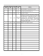
Page 3: ...700 002 38 40 05700 002 38 34 replaced with 05700 003 02 98 05700 003 04 64 05700 003 02 71 Replace reed switch 05930 111 41 70 with 05930 002 36 80 Add the following components to the PA 1V Plumbing bracket 05700 002 28 95 frame weldment 05700 002 97 85 accumulator weldment 05700 002 19 05 spring rod 05700 002 10 52 Removed interlock solenoid assembly 05700 002 75 85 added 05700 002 66 17 Added P...

Page 4: ... NOMENCLATURE FOR THE MODELS COVERED IN THIS MANUAL PA 1V PA Puritan series chemical sanitizing door type dishmachines PA 1 Single rack dishmachine PA 2 Dual rack dishmachine V Vapor Vent CDL Corner model with left hand entry CDR Corner model with right hand entry ...

Page 5: ...r Parts Kit 26 Vacuum Breaker Repair Parts Kit 30 VI PARTS SECTION Standard Parts 34 Chemical Feeder Pump Assembly 37 Solenoid Valve Assembly 38 Vacuum Breaker Assembly 39 Control Box Assembly 40 Hood Assemblies PA 1 42 Hood Assembly PA 2 43 Cantilever Arm Assembly PA 1 PA 2 Double Bracket Mount 44 Cantilever Arm Assembly PA 1 PA 2 Single Bracket Mount 46 Tub Assembly PA 1 47 Tub Assembly PA 2 Lef...

Page 6: ...ssembly Options 59 PA 2CDR Assembly Options 61 PA 1 Vapor Vent Option Assembly 63 VII SCHEMATICS PA 1 115 Volt 60 Hz single phase 65 PA 1V 115 Volt 60 Hz single phase 66 PA 2 115 Volt 60 Hz single phase 67 PA 2CDL PA 2CDR 115 Volt 60 Hz single phase 68 PA 1 PA 2 Series Installation Operation Manual 7610 002 24 11 Rev J 11 02 2005 ...

Page 7: ...1 SECTION 1 SPECIFICATION INFORMATION ...

Page 8: ...ed upon 1 125 of the full amperage load of the machine and 2 typical fixed trip circuit breaker sizes as listed in the NEC 2002 Edition Local codes may require more stringent protec tion than what is displayed here Always verify with your electrical service contractor that your circuit protection is adequate and meets all applicable national and local codes These numbers are provided in this manua...

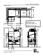
Page 9: ...FIGURATION 5 MIN TOP VIEW RACK GUIDES IN CORNER CONFIGURATION 24 1 4 DOORS 19 MAX CLEARANCE 34 TABLE HEIGHT 1 1 RIGHT SIDE NOTE DRAIN IS ON FAR SIDE OF ACCUMULATOR 4 MIN 12 1 2 B B A C 61 62 A Drain Connection 2 NPT B Electrical Connection 3 4 Conduit C Water Inlet 3 4 NPT ALL DIMENSION FROM FLOOR ARE ADJUSTABLE 1 2 DUE TO BULLET FEET 32 1 4 6 FRONT 34 TABLE HEIGHT 11 1 2 A 25 1 4 25 1 4 12 ...

Page 10: ...v J 11 02 2005 00000000 TOP VIEW FRONT VIEW RIGHT SIDE VIEW A WATER INLET 3 4 NPT B DRAIN CONNECTION 2 NPT C ELECTRICAL CONNECTION ALL DIMENSION FROM FLOOR ARE ADJUSTABLE 1 2 DUE TO BULLET FEET 25 7 8 1 66 59 56 1 2 61 10 5 8 75 3 4 44 1 8 4 1 2 min 4 3 4 15 3 4 13 1 8 A A C C B B A 34 TABLE HEIGHT 17 1 2 MAX CLEARANCE ...

Page 11: ...ENSIONS PA 2CDL 00000000 20 3 4 OPENING 4 1 2 MINIMUM 2 1 2 1 1 2 19 OPENING 20 3 4 OPENING 2 1 2 3 1 2 4 MINIMUM 2 1 2 A DRAIN GRAVITY 2 NPT B WATER INLET 3 4 NPT C ELECTRICAL CONNECTION 3 4 ALL DIMENSION FROM FLOOR ARE ADJUSTABLE 1 2 DUE TO BULLET FEET 32 3 4 25 3 4 43 1 2 46 1 2 A C B B 16 13 66 1 4 60 3 4 12 34 77 14 ...

Page 12: ... J 11 02 2005 19 OPENING 12 3 8 2 1 2 2 1 2 20 3 4 OPENING 4 1 2 MINIMUM 1 1 2 20 3 4 OPENING 2 1 2 4 MINIMUM 3 1 2 A DRAIN GRAVITY 2 NPT B WATER INLET 3 4 NPT C ELECTRICAL CONNECTION ALL DIMENSION FROM FLOOR ARE ADJUSTABLE 1 2 DUE TO BULLET FEET 32 3 4 25 3 4 43 1 2 46 1 2 30 1 2 16 C C B B A A 77 60 3 4 66 1 4 34 12 12 14 ...

Page 13: ...ENSIONS CONNECTION TO DISHMACHINE TABLE DIMENSIONS STRAIGHT THROUGH INSTALLATION 20 1 2 OPENING 25 1 4 2 1 4 4 MIN 2 1 2 4 MIN 20 1 2 OPENING 25 1 4 20 1 2 3 4 1 1 2 ROLL 4 MIN 2 1 2 25 1 4 20 1 2 OPENING 25 1 4 PA 1 44 PA 2 PA 1 PA 2 Series Installation Operation Manual 7610 002 24 11 Rev J 11 02 2005 ...

Page 14: ...SECTION 2 INSTALLATION OPERATION INSTRUCTIONS 8 ...

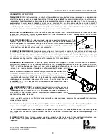
Page 15: ...ain is a gravity discharge drain All piping from the 2 MNPT connection on the waste accumulator must be pitched 1 4 per foot to the floor or sink drain All piping from the machine to the drain must be a minimum 2 NPT and shall not be reduced There must also be an air gap between the machine drain line and the floor sink or drain If a grease trap is required by code it should have a flow capacity o...

Page 16: ...d grounding lug Install the service wires L1 L2 to the appro priate terminals as they are marked on the terminal block Install the grounding wire into the lug provided Tighten the connections It is recommended that DE OX or another similar anti oxidation agent be used on all power connections VOLTAGE CHECK Ensure that the power switch is in the OFF position and apply power to the dishmachine Check...

Page 17: ... upon which way it is depressed 3 To prime the pumps hold the switch in the momentary position until chemical can be observed entering the sump 4 Detergent is dispensed as required during the wash cycle by the cam timer The amount of detergent may need to be increased or decreased depending on water quality and type of detergent It is adjusted by changing Cam 6 on the cam timer 5 Rinse additive is...

Page 18: ...uired If the water pressure is correct then the fill valve cam will need adjustment Use the following steps to adjust the cam A Turn power off at the machine circuit breaker B Open control box cover C Locate the timer fill valve cam Cam 4 from the timer motor D Locate the spanner wrench taped to the electrical panel The spanner wrench is used to adjust the cam E To increase the water level open th...

Page 19: ...ng A Open door and verify that the sump strainer is in place in the sump B Verify that the drain stopper is in position C Check that the plugs are securely screwed into the ends of all wash arms D Check that the wash arms are securely screwed into the stationary bases and rotate freely E Check levels in all chemical containers and replace if empty F For initial fill close doors then depress the OF...

Page 20: ...the dwell period Any adjustment made to the drain should be made to the left side of cam 3 The cam must be moved back into the wash time until all of the water is drained from the machine CAM 4 Cam 4 is an adjustable cam and controls the fill valve and therefore the rinse cycle FUNCTION The fill valve cam works off the normally closed contacts of cam 4 This requires the switch to be held open by t...

Page 21: ...stable cam and controls the rinse aid pump FUNCTION The rinse aid pump cam works off the normally closed contacts of cam 7 This requires the switch arm to be held open by the cam and allowed to drop into the notch to operate the pump The time that the rinse aid pump will remain energized must be determined in the field to suit the chemical used and water conditions SETTINGS The left side of cam 7 ...

Page 22: ...16 SECTION 2 INSTALLATION OPERATION INSCTRUCTIONS TIMING CHART PA 1 PA 2 MODELS PA 1 PA 2 Series Installation Operation Manual 7610 002 24 11 Rev J 11 02 2005 ...

Page 23: ...s energized injecting rinse aid into wash tank Controlled by C7 cam 58 SECONDS INTO CYCLE Sanitizer pump is de energized The length of time that the sanitizer pump is activated will be determined in the field Timing will depend on the chemical used and water conditions Controlled by C5 cam 60 SECONDS INTO CYCLE Rinse aid pump is de energized The length of time that the rinse aid pump is activated ...

Page 24: ...18 SECTION 3 PREVENTATIVE MAINTENANCE ...

Page 25: ...hine could lead to larg er problems or even cause harm to the operator If a problem is discovered secure the dishmachine using proper shut down procedures as listed in this manual and contact your Puritan representative Some problems however may having nothing to do with the machine itself and no amount of preventative maintanence is going to help A common problem has to do with temperatures being...

Page 26: ...20 SECTION 4 TROUBLESHOOTING ...

Page 27: ... cam timer is not rotating check the voltage to the motor If voltage is present when the door is closed replace the timer motor 3 Faulty control relay Check the voltage across relay contacts 9 and 6 If 120 volts when the doors is closed replace the relay 4 Faulty NORMAL DELIME switch In the NORMAL position check the voltage between the WHITE BLACK and WHITE RED wires to the NORMAL DELIME switch If...

Page 28: ... GREEN wires If it reads 120 volts adjust or replace the switch Problem Dishmachine fills continuously even without power applied to the machine 1 Solenoid valve dirty or faulty Clean valve or replace faulty parts as required Problem Dishmachine fills continuously only when power is supplied to the machine 1 Faulty fill microswitch Repair or replace switch as necessary 2 Cam timer stalled in fill ...

Page 29: ... connections 2 Faulty door switch or detergent safety switch Check for a loose or wet connection at the switch and wire connectors Bypass the switch to verify that it is indeed the problem Replace the switch if necessary 3 Pump impeller jammed Clear the impeller 4 Wash motor faulty Check the motor voltage and amperage draw If amperage draw is over 12 amps replace the motor Problem Low wash water p...

Page 30: ...the prime switch If it reads 120 volts replace the switch 2 Faulty delime switch With the delime switch in the DELIME position check for voltage between the WHITE BLACK and WHITE RED wires to the delime switch If it reads 120 volts replace the switch Problem Sanitizer pump doesn t run during the cycle or through the prime switch 1 Loose sanitizer pump motor wire Verify and tighten connections to t...

Page 31: ...25 SECTION 5 SERVICE PROCEDURES ...

Page 32: ...tled PREPARATION IMPORTANT NOTES 1 Read these instructions thoroughly before attempting this maintenance evolution Become familiar with the parts and what actions need to be taken This will save time in the long run 2 The procedures demonstrated in this manual are shown being performed on an ES 4400 rack conveyor dish machine The actual maintenance steps however apply to any Parker style solenoid ...

Page 33: ...k up 9 Reconnect the wires from the conduit to the wires from the solenoid as they had been connected previously Ensure that the wire nuts are on tight 10 Slide the coil wire cover back on taking care not to dam age the wires 11 If you are done performing maintenance on the valve con tinue on to step 23 Otherwise please go on to step 12 L 12 To remove the valve bonnet grasp it with the jaws of the...

Page 34: ... though an O ring may not appear damaged it is a good idea to go ahead and replace it if you have a new one This will help ensure that your valve remains leak free in the future 17 Remove the diaphragm retainer and then the diaphragm itself Many problems associated with a solenoid valve can be traced to a clogged pilot port in the diaphragm 18 As indicated in the photo above the extension hole can...

Page 35: ...e AFTER MAINTENANCE ACTIONS Reconnect the incoming water if disconnected and turn on Then restore power to the unit Run the unit for at least 10 minutes to ensure there are no leaks If any problems arise please contact your Puritan representative SPECIAL PARTS Repair kit includes Plunger Spring O ring and Diaphragm 1 2 Repair Kit Part No 85283489 Mfg No N A 3 4 Repair Kit Part No 85283406 Mfg No N...

Page 36: ...not including all of the items indicat ed in the section entitled PREPARATION IMPORTANT NOTES 1 Read these instructions thoroughly before attempting this maintenance evolution Become familiar with the parts and what actions need to be taken This will save time in the long run STEPS 1 Note These instructions only apply to vacuum breakers 1 2 NPT and 3 4 NPT as pictured below The repair kits indicat...

Page 37: ...nt on the cap retainer as well Regardless of the condition of the plunger this O ring should be replaced once the cap is removed Using a small flathead screwdriver remove the old O ring 10 With the new O ring in place screw the cap back on the vacuum breaker body The cap needs to only be hand tight snug AFTER MAINTENANCE ACTIONS 1 Reconnect the incoming water if disconnected and turn on Then resto...

Page 38: ...THIS PAGE IS INTENTIONALLY LEFT BLANK 32 ...

Page 39: ...33 SECTION 5 PARTS SECTION ...

Page 40: ... 24X3 8 05305 173 03 00 88120746 SCREW 10 24X1 2 N A 88120191 SCREW 10 24X3 4 N A 88120019 SCREW 10 24X1 N A 88120000 SCREW 10 24X6 N A 88220007 SCREW SOCKET 1 4 20X3 8 N A 88020433 SCREW 1 4 20X1 2 05305 274 02 00 88000013 SCREW 1 4 20X5 8 05305 274 24 00 88020458 SCREW 1 4 20X3 4 05305 274 04 00 88030069 SCREW 1 4 20X1 1 2 05305 274 23 00 88000104 SCREW 1 4 20X2 1 2 05305 274 13 00 88021027 SCRE...

Page 41: ...1 3 4 N A HARDWARE MISC 83109041 CABLE TIE 7 05975 602 05 16 83109199 CABLE TIE 15 100PK N A 83109025 CABLE TIE W SCREW HOLE N A 89990121 GREASE SILICONE 3OZ TUBE N A 89992176 SILICONE CAULK WHITE 3OZ TUBE N A 89991996 TEFLON TAPE ROLL N A 83109125 ELECTRICAL TAPE N A 96022447 ENDCAP DOOR HANDLE 05340 011 35 00 96552336 DOOR GUIDE PLASTIC 23 1 2 Long 05700 111 33 59 ELECTRICAL 83300541 CONDUIT 1 2...

Page 42: ...20 011 69 05 85220077 REGULATOR WATER 1 2 PIPE 140F 04820 100 04 07 85220010 REGULATOR WATER 3 4 PIPE 180F 04820 100 01 06 85284214 REPAIR KIT 3 4 WATER REGULATOR N A 96027024 STRAINER Y 1 2 PIPE 04730 217 01 10 85300325 STRAINER Y 3 4 PIPE 04730 717 02 06 85300301 SCREEN COARSE 3 4 N A 85300333 SCREEN FINE 3 4 N A TUBING 85015105 TUBING 1 4 CLEAR 05700 011 37 12 85015097 TUBING 1 4 RED 05700 011 ...

Page 43: ...art No 89990121 Squeeze Tube Detergent Sanitizer Use with the red roller Part No 96562673 Mfg No 05700 111 35 29 Clear Squeeze Tube Rinse Aid Use with the white roller Part No 85017119 Mfg No 05700 011 76 41 Tube Small 7 32 Use with the black roller Part No 85016079 Mfg No 05700 011 65 21 Motor 36 RPM 115V Detergent Sanitizer Feeder Pump Part No 83740209 Mfg No 004320 111 35 14 Motor 14 RPM 115V R...

Page 44: ...Diaphragm Retainer Diaphragm O Ring Plunger Spring Screen Retainer Mesh Screen Valve Body 1 2 110 240 Volt Solenoid Valve Complete Assembly Part No 96580683 Mfg No 04810 100 12 18 3 4 110 240 Volt Solenoid Valve Complete Assembly Part No 85260511 Mfg No 04810 100 53 00 Repair kit includes Plunger Spring O ring and Diaphragm 1 2 Repair Kit Part No 85283489 Mfg No N A 3 4 Repair Kit Part No 85283406...

Page 45: ...1 4 Complete Vacuum Breaker Assembly Bottom Inlet Outlet Part No 85242000 Mfg No N A 3 8 Complete Vacuum Breaker Assembly Part No 85242527 Mfg No 04820 002 75 73 Components of 1 2 Repair Kit Part No 85284156 Mfg No 04820 001 60 56 Components of 3 4 Repair Kit Part No 85284164 Mfg No 04820 001 60 57 Data Plate 3 4 Part No 96850342 Mfg No N A 1 2 Cap Part No 85284065 Mfg No N A 3 4 Cap Part No 96560...

Page 46: ... 7610 002 24 11 Rev J 11 02 2005 SECTION 5 PARTS SECTION CONTROL BOX ASSEMBLY PA 1 PA 2 MODELS 00000000 1 40 41 42 2 3 2 13 2 14 2 15 16 17 18 2 5 6 7 8 9 10 2 4 11 12 19 20 23 24 25 31 30 30 28 29 40 41 43 26 27 21 22 33 34 39 43 39 38 35 36 32 37 42 ...

Page 47: ...9905 002 24 48 22 1 Decal Control Box Front PA 2 96582157 09905 002 24 53 23 1 Power Switch 83020461 05930 111 38 79 24 1 Cycle Light 96581814 05945 504 08 18 25 1 Power Light 83630392 05945 504 07 18 26 1 Cycle Counter 83650044 05990 111 35 38 27 2 Screw 4 40 x 1 4 Phillips Pan Head 96023832 05305 002 32 38 28 1 Hole Plug 1 2 83115003 04730 011 60 22 29 1 Hole Plug PA 1 only 96024567 05975 011 47...

Page 48: ...t Front Part No 96550173 Mfg No 05700 021 33 19 Door Guide Left Rear Part No 96550264 Mfg No 05700 021 33 16 Door Guide Right Rear Part No 96550272 Mfg No 05700 021 33 15 Double Door Guide Left Front Part No 96550181 Mfg No 05700 021 33 20 Arm Support Weldment Gasket Part No 965053151 Mfg No 05700 111 36 01 Bracket Cantilever Support 2 per machine Part No 96581244 Mfg No 05700 031 88 00 Wear Butto...

Page 49: ...011 34 63 10 1 Door Catch 96580998 05700 011 46 50 11 1 Hood Stiffener 96585609 05700 002 08 24 12 2 Bracket Cantilever Support 96581244 05700 031 88 00 13 6 Wear Button 96027743 05700 011 88 01 14 1 Door Guide Left Rear New Style 96030457 05700 021 84 71 15 1 Door Guide Right Rear New Style 96030432 05700 021 84 70 HOOD ASSEMBLY PA 2 1 2 3 6 4 5 11 10 9 OLD STYLE If your unit uses items 5 and 6 i...

Page 50: ...A 2 Series Installation Operation Manual 7610 002 24 11 Rev J 11 02 2005 SECTION 5 PARTS SECTION CANTILEVER ARM DOUBLE BRACKET MOUNT 3 5 2 1 6 9 15 16 17 18 19 11 12 20 21 25 22 23 18 7 8 4 24 18 14 13 10 11 12 ...

Page 51: ...96582754 05700 011 90 99 10 2 Screw 1 4 20 x 1 1 2 Long S S 88030069 05305 274 23 00 11 2 Washer 1 4 ID S S 880530589 05311 174 01 00 12 2 Locknut 1 4 20 S S Hex with Nylon Insert Low Profile 96026455 05310 374 02 00 13 2 Sleeve Cantilever Arm 96582770 05700 000 85 69 14 2 Plug Cantilever Arm 96022447 05340 011 35 00 15 1 Magnet Reed Switch 96025200 05930 111 51 68 16 2 Locknut 8 32 S S Hex with N...

Page 52: ... S S 88422068 05310 276 01 00 10 1 Cantilever Arm PA 1 96582879 05700 031 34 35 10 1 Cantilever Arm PA 2 96584297 05700 031 45 38 11 2 Hex Head Bolt 1 4 20 x 1 1 2 S S 88030069 05305 274 23 00 12 4 Washer Flat 1 4 S S 88530589 05311 174 01 00 13 2 Cantilever Arm Sleeve 96582770 05700 000 85 69 14 2 Hex Head Bolt 1 4 20 x 1 2 S S 88020433 05305 274 02 00 15 2 Endcap Cantilever Arm 96022447 05340 01...

Page 53: ...Drain Solenoid Box Cover 96580634 05700 031 33 27 14 1 Drain Solenoid 83999078 04810 200 11 00 15 8 Locknut 10 24 with Nylon Insert 88429063 05310 373 01 00 16 1 Hair Pin 1 2 to 3 4 N A 05315 002 15 39 1 Drain Link Assembly N A 05700 002 38 20 17 1 Nut Hex 5 16 18 88422043 05310 275 01 00 18 1 Drain Link Connector 96028261 05700 002 38 10 19 1 Drain Solenoid Link 96582994 05700 031 34 45 20 1 Spil...

Page 54: ...tor 83710418 06105 121 35 18 7 2 Fitting 3 8 Barbed x 1 8 Male NPT 85196004 04730 111 35 02 8 2 Pump Inlet Nipple 96581202 05700 021 46 84 9 4 Hose Clamp Regular 1 5 16 2 1 4 87301362 04730 719 01 37 10 4 Hose Clamp Mini 7 16 25 32 87301131 04730 011 36 05 11 2 Hose 3 8 ID x 8 1 2 Long 96550439 05700 011 45 30 12 2 Hose 1 1 2 ID x 8 3 4 Long 96583018 05700 011 45 28 13 2 Hose Clamp Regular 5 5 8 6...

Page 55: ...S Hex with Nylon Insert 88429113 05310 374 01 00 1 Drain Link Assembly N A 05700 002 38 21 6 1 Drain Link 96580188 05700 031 46 52 7 1 Drain Link Connector 96028261 05700 002 38 10 8 1 Hex Nut 5 16 18 88422043 05310 275 01 00 9 2 Spillway Gasket 96582903 05700 111 34 52 10 1 Drain Seat Insert Stainless Ring 96582929 05700 021 34 38 11 1 Spillway Weldment 96583000 05700 031 37 86 12 1 Hair Pin 1 2 ...

Page 56: ... 41 PA 1V Frame Weldment Double Bracket Part No N A Mfg No 05700 002 97 85 Bullet Feet Part No 96552666 Mfg No 05340 108 01 03 PA 2 Frame Weldment Part No 96583588 Mfg No 05700 031 45 16 Bullet Feet Part No 96552666 Mfg No 05340 108 01 03 PA 2 Frame Weldment Double Bracket Part No N A Mfg No 05700 002 61 22 PA 1 PA 2 Series Installation Operation Manual 7610 002 24 11 Rev J 11 02 2005 ...

Page 57: ...tor Weldment Part No 96580600 Mfg No 05700 031 62 90 PA 1V Accumulator Weldment Part No 96028717 Mfg No 05700 002 19 05 NOTE This is a rear view of the accumulator as it would appear installed on the dishmachine PA 2 Accumulator Weldment Part No 96021977 Mfg No 05700 031 66 24 Locknut 10 24 S S Hex with Nylon Insert Part No 88429063 Mfg No 05310 373 01 00 PA 2 Accumulator Stop Clip Part No 9604200...

Page 58: ... PARTS SECTION INCOMING PLUMBING ASSEMBLY PA 1 PA 2 SERIES 1 2 3 4 6 7 8 9 4 NOTE Depending on how old your PA 2 unit may be the soldered piece above may be turned in this configuration Overall this will make the plumbing shorter in length and taller in height 4 5 Represents an item not shown ...

Page 59: ... 002 53 77 6 1 3 4 Male NPT x Male Slip Adapter 86559044 04730 401 10 01 7 1 3 4 Solenoid Valve 85260511 04810 100 53 00 8 1 3 4 NPT x 3 Nipple 85141638 04730 011 38 29 9 1 3 4 NPT Y Strainer 85300325 04730 717 02 06 10 1 Bracket Incoming Plumbing Support 96582937 05700 021 34 02 10 1 Bracket Incoming Plumbing Support PA 1V 96028816 05700 002 28 95 11 1 Diverter End Cap 96582172 05700 021 45 32 PA...

Page 60: ... Part No 88521109 Mfg No 05311 276 01 00 Casting Upper Wash Manifold Part No 96583620 Mfg No 05700 031 34 82 Wedge Manifold Casting Used on the PA 2 units only Part No 96583497 Mfg No 09515 011 46 61 Washer 3 8 Bevel Square 2 per assembly Part No 88500000 Mfg No 05311 011 35 36 O Ring 2 per assembly Part No 87203154 Mfg No 05330 111 35 15 Manifold Tube Part No 96550338 Mfg No 05700 031 34 59 Manif...

Page 61: ...1 Gasket 84805944 05330 011 95 18 7 1 Pump Seal 84804723 05330 002 06 21 8 4 Hex Head Bolt 3 8 16 x 3 4 S S 88021027 N A 9 4 Hex Head Bolt 3 8 16 x 1 1 4 S S 88021050 N A 10 1 Bracket Motor to Pump ECL 9 96583810 N A 11 1 Slinger Pump Shaft 96031059 N A 12 1 Shaft Adapter Connector ECL 6 96562764 N A 13 2 Allen Head Setscrew 1 4 20 x 1 4 88220007 N A 14 1 Pump Motor 83710418 06105 121 35 18 15 1 P...

Page 62: ...7475 Mfg No 05700 121 35 54 PA 1 Rack Guide Assembly Part No 96582887 Mfg No 05700 031 36 76 PA 2 Injection Tube Weldment Part No 96550371 Mfg No 05700 031 46 78 PA 2 Injection Tube Gasket Part No 96562954 Mfg No 05700 011 45 36 PA 2 Injection Tube Bushing Part No 96033063 Mfg No 05975 002 47 54 PA 1 Intake Pump Strainer Weldment Part No 96582029 Mfg No 05700 002 60 50 Reed Switch 1 per machine Pa...

Page 63: ...0 002 67 71 PA 1 Right Door Part No 96582169 Mfg No 05700 002 38 91 PA 1V Right Door Part No N A Mfg No 05700 003 13 03 Locknut 8 32 S S Hex with Nylon Inset Part No 88429105 Mfg No 05310 272 02 00 Door Guides Part No 96552336 Mfg No 05700 111 33 59 Magnet Part No 96025200 Mfg No 05930 111 51 68 PA 1 Optional Front Door Handle Service Only Part No 96041132 Mfg No 05700 002 51 56 Door Connector Bra...

Page 64: ...Door Weldment Part No N A Mfg No 05700 003 04 64 Right Door Part No N A Mfg No 05700 003 02 71 Locknut 8 32 S S Hex with Nylon Inset Part No 88429105 Mfg No 05310 272 02 00 Door Guides Part No 96552336 Mfg No 05700 111 33 59 Magnet Part No 96025200 Mfg No 05930 111 51 68 PA 2 Door Stop Part No 96558671 Mfg No 05700 011 46 30 Door Connector Bracket Part No 96582820 Mfg No 05700 021 33 39 ...

Page 65: ... SECTION 5 PARTS SECTION PA 2CDL ASSEMBLY OPTIONS 1 2 10 6 00000000 9 12 21 22 13 19 20 3 11 7 10 3 A 4 5 A 8 15 16 17 18 14 PA 1 PA 2 Series Installation Operation Manual 7610 002 24 11 Rev J 11 02 2005 ...

Page 66: ...30 111 51 68 2 Locknut 8 32 Hex with Nylon Insert 88429105 05310 272 02 00 10 2 Front Door Guide 96583570 05700 021 44 94 11 1 Bracket Side Door Connecting 96033626 05700 002 07 33 12 1 Right Rear Door Guide 96030432 05700 021 84 70 13 2 Bolt Hanger Eye 96582762 05306 956 05 00 14 1 Chemical Feed Tube Weldment 96041066 05700 002 08 14 1 Gasket Chemical Feed Tube 96562954 05700 011 45 36 1 Bushing ...

Page 67: ...61 PA 1 PA 2 Series Installation Operation Manual 7610 002 24 11 Rev J 11 02 2005 SECTION 5 PARTS SECTION PA 2 CDR ASSEMBLY OPTIONS 1 3 19 17 16 9 20 21 22 18 5 24 4 10 2 A 6 7 B 8 15 16 17 18 14 ...

Page 68: ... 05700 111 33 59 1 Magnet Reed Switch 96025200 05930 111 51 68 2 Locknut 8 32 Hex with Nylon Insert 88429105 05310 272 02 00 11 1 Chemical Feed Tube Weldment 96041066 05700 002 08 14 1 Gasket Chemical Feed Tube 96562954 05700 011 45 36 1 Bushing 3 4 Hole Snap 96033063 05975 002 47 54 Rack Rail Assembly 96041009 05700 002 08 85 12 1 Rack Rail Weldment N A 05700 002 07 64 13 3 Locknut 10 24 Hex S S ...

Page 69: ... No 96627506 Mfg No 05330 002 75 06 Vapor Vent Incoming Plumbing Assembly 1 per assembly Part No 96627752 Mfg No 05700 002 77 52 Solenoid Valve 3 8 115V 1 per assembly Part No N A Mfg No 04730 002 75 48 Nipple 3 8 Close NPT 1 per assembly Part No 85140804 Mfg No 04730 002 18 00 Elbow 3 8 90 Street 1 per assembly Part No 86078052 Mfg No 04730 002 15 36 Vacuum Breaker 3 8 1 per assembly Part No 8528...

Page 70: ...SECTION 6 ELECTRICAL SCHEMATICS 64 ...

Page 71: ...65 PA 1 PA 2 Series Installation Operation Manual 7610 002 24 11 Rev J 11 02 2005 Revised October 29 2007 SECTION 6 ELECTRICAL SCHEMATICS PA 1 115 VOLT 60HZ SINGLE PHASE ...

Page 72: ...66 PA 1 PA 2 Series Installation Operation Manual 7610 002 24 11 Rev J 11 02 2005 SECTION 6 ELECTRICAL SCHEMATICS PA 1V 115 VOLT 60HZ SINGLE PHASE ...

Page 73: ...67 SECTION 6 ELECTRICAL SCHEMATICS PA 2 115 VOLT 60HZ SINGLE PHASE PA 1 PA 2 Series Installation Operation Manual 7610 002 24 11 Rev J 11 02 2005 ...

Page 74: ...68 SECTION 6 ELECTRICAL SCHEMATICS PA 2CDL PA 2CDR 115 VOLT 60HZ SINGLE PHASE PA 1 PA 2 Series Installation Operation Manual 7610 002 24 11 Rev J 11 02 2005 ...

Page 75: ......

Reviews: