background image

37

07610-002-23-32-AD

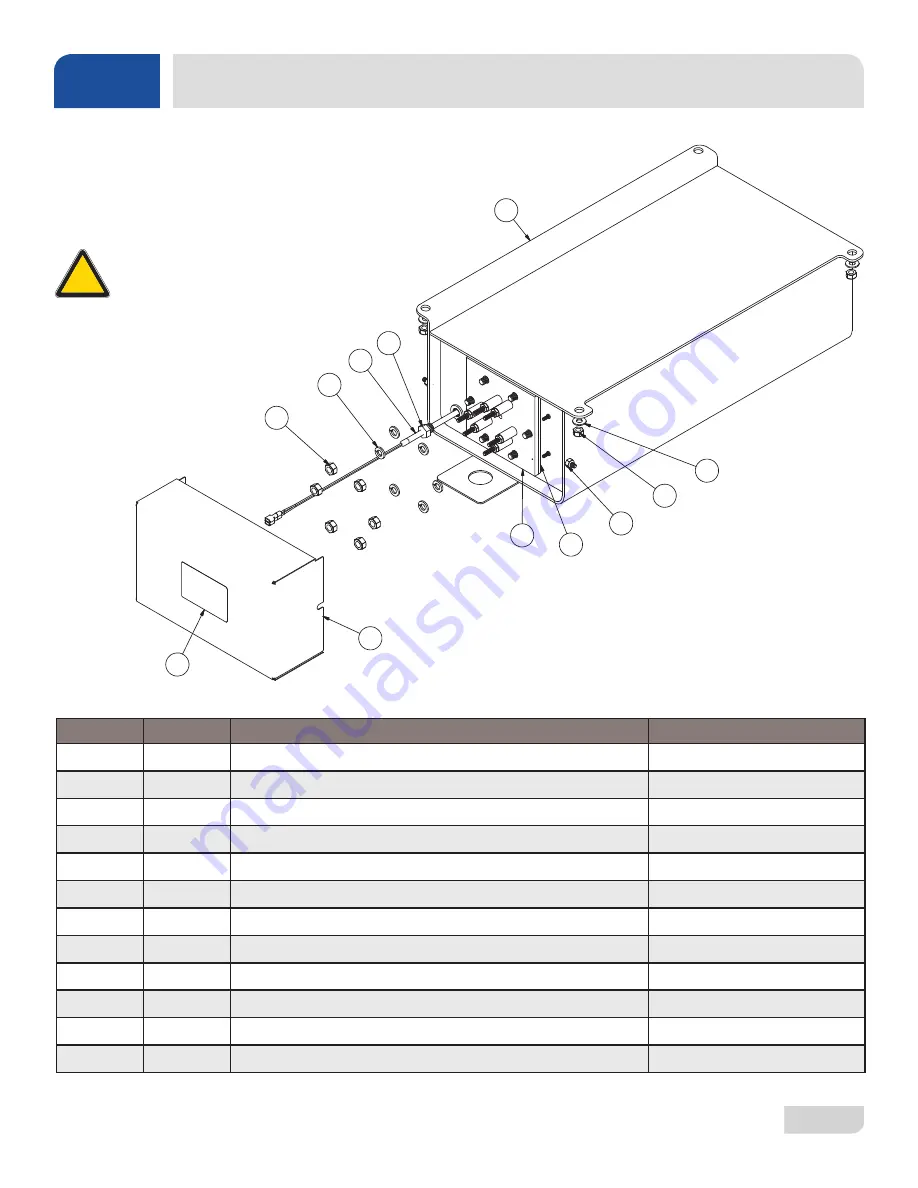
ITEM

QTY

DESCRIPTION

PART NUMBER

1

1

Tank, Rinse

05700-002-10-19

2

1

Gasket, Rinse Heater 

05330-200-02-70

3

1

Heater, Rinse

See "Heaters" page.

4

1

Probe, Thermistor 4" 

06685-004-17-26

5

1

Fitting, Thermostat Brass

05700-011-73-73

6

6

Nut, Hex, 5/16-18

05310-275-01-00

7

6

Lockwasher, 5/16", Split

05311-275-01-00

8

2

Locknut, 10-24 with Nylon Insert

05310-373-01-00

9

4

Locknut, 1/4-20 with Nylon Insert

05310-374-01-00

10

4

Washer, 1/4", Flat

05311-174-01-00

11

1

Cover, Rinse Tank 

05700-002-16-51

12

1

Decal, Warning-Disconnect Power

09905-004-08-16

Complete Assemblies

208-230 V, 14 kW 70◦


Rise  -  06401-004-55-19

208-230 V, 12 kW 40◦ Rise  -  06401-004-55-20
460 V, 14 kW 70◦ 

Rise  

-  06401-004-55-21

460 V, 12 kW 40◦ Rise  -  06401-004-55-22

RINSE TANK 

PARTS

CAUTION!

 HH-E & HH-E-VER 

machines with serial numbers after 

18C355287 have the rinse tank on 

the previous page. 

!

CAUTION

Summary of Contents for TEMPSTAR HH-E

Page 1: ...TEMPSTAR HH E INSTALLATION OPERATION AND SERVICE MANUAL TempStar HH E Manual 07610 002 23 32 AD TEMPSTAR SERIES DOOR TYPE DISHMACHINES...

Page 2: ...led by Jackson at the factory and are shipped with the Dishmachine carry only a 1 one year parts warranty Labor to repair or replace these components is not included in the warranty or covered by Jack...

Page 3: ...DEFECTS IN MATERIALS AND WORKMANSHIP AND IS REPORTED TO JACKSON WITHIN 30 THIRTY DAYS FROM THE DATE OF INSTALLATION 9 DAMAGE CAUSED BY LABOR DISPUTE 10 DAMAGES RESULTING FROM IMPROPER CONNECTION TO U...

Page 4: ...etpoint instructions L 1 10 13 RLC 8252 Updated schematic and control box to reflect rotary switch M 3 7 13 RLC QOF NDB 219 Updated Jackson logo and company name N 3 24 14 MHH Updated warranty page Re...

Page 5: ...matics Updated to new manual format Audited and corrected all P Ns in the manual AC 9 9 17 JH 8541 8543 Added the TempStar HH E and associated parts and assemblies Moved door switch from the Tub Assem...

Page 6: ...itizing no rinse booster TempStar HH S Door type dishmachine steam heated high temp hot water sanitizing The manufacturer provides technical support for all of the machines detailed in this manual We...

Page 7: ...packing 8 HH E VER Assembly 8 Leveling 8 Plumbing 8 Water Supply Connection 8 Steam Line Connection 9 Pressure Regulator 9 Shock Absorber 9 Connecting the Drain Line 9 Exhaust Fan Timer 9 Chemical Con...

Page 8: ...ction 14 Shutdown Cleaning 14 VER Coil Cleaning 16 Detergent Control 17 Deliming 18 MAINTENANCE Preventative Maintenance 19 TROUBLESHOOTING Common Problems 20 PARTS Control Box 22 Hood 26 Door Arm 28...

Page 9: ...Door Interlock Override 55 460 V Machine Transformer Mounting Box 56 Kits 57 SCHEMATICS HH E HH E VER 208 230 V New Rinse Tank 58 HH E HH E VER 460 V New Rinse Tank 59 HH E HH E VER 208 230 V Old Rin...

Page 10: ...ink ANSI American National Standards Institute Btu Hr British Thermal Units per Hour CFM Cubic Feet per Minute GHT Garden Hose Thread GPH Gallons per Hour GPM Gallons per Minute GPG Grains per Gallon...

Page 11: ...863 4 2203 mm WITH DOOR OPEN A 73 1854 mm 17 432 mm C B 28 5 8 727 mm 25 635 mm 1 4 15 387 mm LEGEND A Drain 1 1 2 NPT B Water Inlet 3 4 NPT C Electrical Connection increased 2 using the machine s ad...

Page 12: ...m 73 1856mm 34 861mm 93 2362mm B 88 2235mm C 10 mm 51 4 134mm LEGEND A Drain 1 1 2 NPT B Water Inlet 3 4 NPT C Electrical Connection increased 2 using the machine s adjustable feet 4 2 85 8 72 7 mm CL...

Page 13: ...1 4 210 mm Distance from wall to rear rack rail Distance from wall to right rack rail Control Panel 1 1 4 32 mm 1 3 8 35 mm 20 1 2 521 mm OPENING 30 762 mm 8 1 4 210 mm 20 1 2 521 mm OPENING 4 102 mm...

Page 14: ...SI 10 2 Water Line Size NPT 1 2 Drain Line Size NPT 1 1 2 TempStar HH E VER Wash Temperature minimum F C 155 68 Rinse Temperature minimum F C 180 83 Inlet Water Temperature F C 40 90 4 4 32 2 Flow Pre...

Page 15: ...OP 208 1 60 Hz 11 2 A 19 7 A 43 3 A 74 2 A 77 0 A 85 0 A 230 1 60 Hz 11 2 A 21 8 A 47 9 A 80 9 A 83 7 A 90 0 A 208 3 60 Hz 11 2 A 11 4 A 25 0 A 47 6 A 50 4 A 60 0 A 230 3 60 Hz 11 2 A 12 6 A 27 7 A 51...

Page 16: ...HH E NB Volts Phase Freq Wash Motor Wash Heater Rinse Heater Total Load MCA MOP 208 1 60 Hz 11 2 A 19 7 A N A 30 9 A 33 7 A 40 0 A 230 1 60 Hz 11 2 A 21 8 A N A 33 0 A 35 8 A 45 0 A 208 3 60 Hz 11 2...

Page 17: ...nit comes with four adjustable bullet feet which can be turned using a pair of channel locks or by hand if the unit can be raised safely Ensure that the unit is level from side to side and front to ba...

Page 18: ...ressure with flow pressure Static pressure is the line pressure in a no flow condition all valves and services are closed Flow pressure is the pressure in the fill line when the fill valve is opened d...

Page 19: ...or and replacing it with the appropriate dispensing equipment See Plumbing HH E VER page for a depiction of the VER rinse injector Rinse aid Using deionized water or other aggressive fluids will resul...

Page 20: ...mproperly connecting external devices can cause damage to the machine and or electrical infrastructure Click here for a wiring guide On 3 Phase machines only correct pump motor rotation must be verifi...

Page 21: ...cted with these higher temperatures in mind Any damage to surrounding area caused by heat moisture to materials that are not recommended for higher temperatures will not be covered under warranty or b...

Page 22: ...b is filled the unit is ready for operation Proper ware preparation will help ensure good results and fewer re washes If not prepared properly ware might not come out clean and the efficiency of the m...

Page 23: ...utomatically Once the cycle is complete open the door again watching for the dripping hot water and remove the rack of clean ware Replace with a rack of soiled ware and close the door Repeat this proc...

Page 24: ...Remove the sump strainer and scrap screen 5 Use a hand scraper to scrape foodsoil into a trash basket 6 Rinse with pre rinse hose and replace 7 Remove all wash and rinse arms 8 Remove the end caps fro...

Page 25: ...t interior of the machine 14 Replace wash and rinse arms 15 Ensure sump strainer and scrap screen are clean and securely in place 16 Use stainless steel polish to clean and protect outside of machine...

Page 26: ...Discuss this option with a qualified water treatment specialist 4 Machine operators should be properly trained on how much detergent is to be used per cycle Meet with a water treatment specialist and...

Page 27: ...cal supplier 6 Flip the mode switch to AUTO to shut the unit off 7 Open the door and step away for five minutes 8 Inspect the inside of the machine If the machine is not delimed run again 9 When clean...

Page 28: ...all strainers are clean and securely in place before operating the machine When cleaning out strainers do NOT beat them on waste cans Wipe out strainers with a rag and rinse with water if necessary Us...

Page 29: ...er is faulty 2 Wash motor faulty damaged 3 Wash motor contactor faulty 1 Verify the timer is receiving power If so replace the timer assembly 2 Verify the wash motor is getting power If so replace the...

Page 30: ...ter Door will not close completely 1 Improper spring tension 2 Obstruction in door channel 3 Door panels are not square with frame 1 Adjust spring tension as required by loosening not removing spring...

Page 31: ...AID DISPENSER CONNECTION DETERGENT DISPENSER CONNECTION LIVE WHEN MACHINE POWER SWITCH IS ON LIVE WHEN RINSE VALVE IS OPEN LIVE WHEN WASH PUMP MOTOR IS ON L1 OUT L2 OUT FUSE 3 AMP SLOW ACTING L1 OUT...

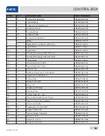
Page 32: ...23 07610 002 23 32 AD 13 9 10 42 40 41 12 15 11 14 27 8 39 37 6 2 6 7 6 5 32 16 31 6 6 6 4 23 24 6 20 18 17 CONTROL BOX PARTS 17 18 6 20 8 2 7 6 6 5 32 16 6 6 23 24 4 4 6 6 31 37 39 43...

Page 33: ...150 F Min 09905 002 97 61 15 1 Decal Rinse 180 F Min 09905 002 97 62 16 1 Ground Lug 05940 200 76 00 17 1 Bracket Liquid Level Control Board 05700 002 13 22 18 1 Liquid Level Control Board 06680 200 0...

Page 34: ...32 x 1 Not Shown 05305 002 19 42 40 1 Switch Rotary Selector 05930 003 97 61 41 1 Switch Operation 05930 301 53 00 42 1 Switch Power 05930 011 49 55 43 1 Exhaust Fan Timer One Shot 05945 004 34 92 43a...

Page 35: ...07610 002 23 32 AD 26 1 5 4 2 3 6 7 10 8 9 HOOD PARTS...

Page 36: ...05700 031 76 33 7 34 Locknut 1 4 20 Hex with Nylon Insert 05310 374 01 00 8 26 Washer 1 4 20 05311 174 01 00 9 6 Screw 1 4 20 x 5 8 Hex 05305 274 24 00 10 20 Bolt 1 4 20 x 1 2 05305 274 02 00 HOOD PAR...

Page 37: ...07610 002 23 32 AD 28 DOOR ARM PARTS 9a 9b 9b 9c 9d 9e 3 See previous page Before ordering door or arm parts see the note on the next page NOTICE...

Page 38: ...ng 05700 002 00 91 11 4 Plate Spring Multiplier 05700 002 00 88 12 4 Spring Cantilever Door 05340 111 35 22 13 2 Bolt Cantilever Hanger Eye 3 8 16 05306 956 05 00 14 2 Washer Impeller 05311 176 02 00...

Page 39: ...07610 002 23 32 AD 30 TUB PARTS 12 11 10 13 15 11 14 34 37 36 33 26 35 31 30 29 27 28 24 25 22 23 21 4 20 19 18 16 16 17 3 1 2 3 5 6 7 9 38 32 8 19b 19c 19a...

Page 40: ...ot Shown 05700 002 91 55 13b 1 Ball Stop Lift Not Shown 05700 002 91 54 14 1 Overflow Support Bracket 05700 001 27 55 14a 1 Shim Overflow Support Not Shown 05700 002 96 48 15 1 O ring 05330 400 05 00...

Page 41: ...00 30 1 Cover Wash Heater 05700 031 47 57 31 1 Decal Warning Disconnect Power 09905 004 08 16 32 1 Harness 5 Connector 05700 004 23 78 33 1 Thermostat Mounting Bracket 05700 004 22 17 34 1 Wash Heater...

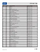
Page 42: ...21 4 20 19 18 16 16 17 3 1 2 3 5 6 7 9 30 24 26 32 33 31 35 34 8 STEAM TUB PARTS ITEM QTY DESCRIPTION PART NUMBER 1 1 Tub Weldment HH Steam 05700 002 63 13 2 1 Track Assembly 05700 002 01 00 3 2 Bulk...

Page 43: ...4 04730 719 01 37 17 1 Discharge Hose 05700 011 88 24 18 1 Nipple 05700 021 34 84 19 1 Pump Support Bracket Assembly See Item 19 on Tub pages 20 1 Clamp Hose 5 5 8 to 6 04730 011 34 90 21 1 Connector...

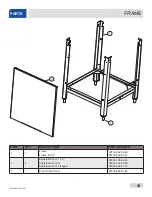
Page 44: ...TY DESCRIPTION PART NUMBER 1 1 Frame Frame 460 V 05700 002 03 49 05700 002 62 41 2 4 Adjustable Foot 1 1 2 Adjustable Foot 3 Adjustable Foot Flanged 05340 108 02 06 05340 002 14 55 05340 002 01 15 3 1...

Page 45: ...t Thermostat 05700 004 36 84 12 2 Nut 1 4 20 05310 004 23 96 13 4 Washer 1 4 20 05311 174 01 00 14 4 Locknut 1 4 20 Hex with Nylon Insert 05310 374 01 00 15 1 Clamp Wire 1 8 P clip 05975 601 10 15 16...

Page 46: ...knut 10 24 with Nylon Insert 05310 373 01 00 9 4 Locknut 1 4 20 with Nylon Insert 05310 374 01 00 10 4 Washer 1 4 Flat 05311 174 01 00 11 1 Cover Rinse Tank 05700 002 16 51 12 1 Decal Warning Disconne...

Page 47: ...00 021 41 38 2 1 Stand C Steam Coil Support 05700 002 08 52 3 1 Stand D Steam Coil Support 05700 002 08 53 4 1 Gasket Steam Coil 05700 001 17 86 5 2 Washer Steam Coil 05700 001 17 87 6 2 Adapter Steam...

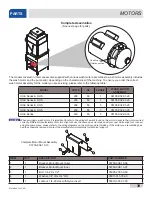
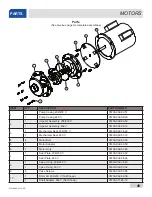
Page 48: ...is important to refer to the wiring schematic found on the motor to ensure the motor is wired correctly Different manufacturers of motors might not use the same wire color codes and your new motor mig...

Page 49: ...al 460 V 05330 002 87 16 4 4 Motor Bolt 05700 002 82 55 5 1 Motor Adapter 05330 002 82 53 6 1 Motor Only 06105 002 82 60 7 1 Seal Plate 208 230 V 05700 002 82 52 1 Seal Plate 460 V 05700 002 06 22 8 1...

Page 50: ...540 121 63 39 TempStar HH E Volts Hz Phase Wash Heater Rinse Heater 14 kW 208 50 1 04540 121 47 39 04540 121 63 38 208 50 3 04540 121 47 39 04540 121 63 38 208 60 1 04540 121 47 39 04540 121 63 38 208...

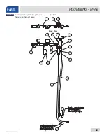
Page 51: ...07610 002 23 32 AD 42 PLUMBING HH E PARTS Top View Back View Before ordering plumbing parts see the note on the next page NOTICE...

Page 52: ...asket Rinse Manifold 05330 003 75 91 When servicing plumbing components take care not to damage the threads of each individual item Damaged threads can cause leaks and loss of pressure which could adv...

Page 53: ...07610 002 23 32 AD 44 PLUMBING HH E VER PARTS APPROX 45 BACK OF MACHINE 13 14 Before ordering plumbing parts see the note on the next page NOTICE...

Page 54: ...07 37 14 1 Gasket Rinse Injector 05330 111 42 81 When servicing plumbing components take care not to damage the threads of each individual item Damaged threads can cause leaks and loss of pressure whi...

Page 55: ...ucing 3 4 to 1 2 04730 911 02 34 Union 3 4 NPT Black Iron 2 per assembly 04730 912 01 01 3 4 NPT Black Iron Pipe 05700 002 20 83 Gate Valve 3 4 NPT 04820 100 19 00 Bracket Steam Plumbing Support 05700...

Page 56: ...Black Iron Pipe 05700 002 20 83 Gate Valve 3 4 NPT 04820 100 19 00 Bracket Steam Plumbing Support 05700 002 20 83 Y Strainer 3 4 NPT Black Iron 04730 217 01 32 Solenoid Valve Steam Plumbing 220V 04820...

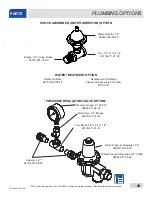
Page 57: ...27 00 Nipple 1 2 Close Brass 04730 207 15 00 SHOCK ABSORBER WATER ARRESTOR OPTION Pressure Gauge 0 100 PSI 06685 111 88 34 Ball Valve 1 4 Bronze 04810 011 72 67 Water Pressure Regulator 1 2 04820 100...

Page 58: ...ragm Retainer Diaphragm 06401 003 07 42 Screen Retainer Mesh Screen Valve Body Complete 240 Volt Solenoid Valve Assembly 04810 100 03 18 Coil Housing only 06401 003 07 44 Complete Vacuum Breaker Assem...

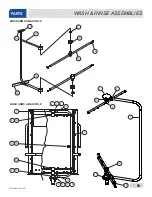
Page 59: ...1 12 15 15 2 3 4 5 7 17 8 6 18 18 18 18 18 2 3 19 5 21 9 18 1 7 21 17 10 1 5 9 WASH RINSE ASSEMBLIES PARTS 16 16 16 16 17 11 13 14 1 10 5 9 7 19 15 2 3 4 5 1 16 9 16 6 15 8 19 7 2 3 12 5 17 18 RINSE A...

Page 60: ...05700 004 54 71 13 2 Complete Rinse Arm Assembly 05700 004 47 74 2 Rinse Arm 05700 004 47 56 14 4 Rinse Arm End cap 04730 111 60 41 15 1 Lower Wash Manifold Weldment 05700 002 21 70 16 5 Locknut 1 4...

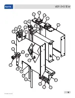
Page 61: ...07610 002 23 32 AD 52 VER SYSTEM PARTS 18 24 23 12 11 16 17 14 21 22 20 19 27 28 29...

Page 62: ...003 06 13 12 1 Elbow 1 2 90 degree Street Brass 04730 206 08 00 13 1 Bracket Vacuum Breaker 05700 004 18 91 14 1 Shroud Heat Exchanger 05700 004 18 92 15 6 Locknut 10 24 Hex with Nylon Insert 05310 37...

Page 63: ...04820 004 24 11 5 1 Spring Compression 05935 004 24 10 6 1 Base Door Interlock Box 05700 004 24 25 7 8 Screw 3 8 Pan Head 05305 171 02 00 8 8 Washer Flat 10 05311 173 02 00 9 2 Locknut 1 4 20 05310 3...

Page 64: ...ck option These instructions should only be used if the door interlock fails to unlatch and the doors won t open 1 Turn machine off by flipping the power switch to OFF 2 If this doesn t disengage the...

Page 65: ...NSFORMER MOUNTING BOX PARTS 460 V Transformer 05950 111 65 93 2 A Circuit Breaker 05925 111 64 18 Transformer Mounting Box 05700 002 10 01 Transformer Mounting Box Top Not Shown 05700 000 78 53 Transf...

Page 66: ...t 06401 004 03 23 Door Magnet Cover Kit 06401 004 07 73 Drain Water Tempering Kit 06401 004 07 86 Exhaust Fan Contactor Kit 05700 004 35 35 False Panel Kit 05700 002 52 89 Phase Conversion Kit 06401 0...

Page 67: ...07610 002 23 32 AD 58 SCHEMATICS HH E VER 208 230 V NEW RINSE TANK...

Page 68: ...59 07610 002 23 32 AD SCHEMATICS HH E VER 460 V NEW RINSE TANK...

Page 69: ...07610 002 23 32 AD 60 SCHEMATICS HH E VER 208 230 V OLD RINSE TANK...

Page 70: ...61 07610 002 23 32 AD SCHEMATICS HH E VER 460 V OLD RINSE TANK...

Page 71: ...07610 002 23 32 AD 62 SCHEMATICS NB 208 230 V...

Page 72: ...63 07610 002 23 32 AD SCHEMATICS NB 460 V...

Page 73: ...07610 002 23 32 AD 64 SCHEMATICS HH S 208 230 V...

Page 74: ...65 07610 002 23 32 AD SCHEMATICS SDI OPTIONS...

Page 75: ......

Page 76: ...Jackson WWS Inc 6209 N US Hwy 25E Gray KY 40734 USA 1 888 800 5672 www jacksonwws com TempStar HH E Manual 07610 002 23 32 AD...

Reviews: