background image

33

07610-003-61-42-U

CANTILEVER ARM/DOOR ASSEMBLIES

PARTS

ITEM

QTY

DESCRIPTION

PART NUMBER

1

1

Cantilever Arm

05700-031-50-67

2

2

Spring Pin, 1/4" x 1 1/8"

05315-407-06-00

3

2

Yoke Assembly 

05700-000-75-77

   3a

1

Cotter Pin

05315-207-01-00

   3b

1

Yoke

05700-000-75-78

   3c

1

Clevis Pin, 5/16” x 1 3/8”

05315-700-01-00

   3d

2

Nylon Washer

05311-369-03-00

   3e

1

Bushing

03120-100-03-00

   3f

2

Locknut, 3/8-16 Hex Center 

05310-256-04-00

4

2

Rod, Spring

05700-003-67-39

5

2

Spring

05340-109-02-00

6

2

Bolt, Cantilever Hanger Eye 3/8-16 

05306-956-05-00

7

2

Washer, 3/8" ID x 7/8" OD

05311-176-02-00

8

4

Nut, 3/8-16  S/S Hex

05310-276-01-00

9

2

Connector, Cantilever Arm

05700-011-90-99

10

2

Screw, 1/4-20 x 1 1/2" 

05305-274-23-00

11

4

Washer, 1/4" 

05311-174-01-00

12

4

Locknut, 1/4-20 Hex with Nylon Insert Low Profile

05310-374-02-00

13

2

Sleeve, Cantilever Arm

05700-000-85-69

14

2

Plug, Cantilever Arm

05340-011-35-00

15

1

Magnet, Reed Switch

05930-111-51-68

16

2

Locknut, 8-32 Hex with Nylon Insert

05310-272-02-00

17

1

Door, Right Side (Complete Assembly)

05700-004-07-47

1

Door, Right Side Weldment with Studs

05700-002-29-85

18

6

Door, Guides

05700-111-33-59

19

2

Screw, 1/4-20 x 1/2" 

05307-011-36-96

20

2

Spacer, PB Bolt

05700-000-29-40

21

4

Locknut, 1/4-20 Hex with Nylon Insert (Not Shown)

05310-374-01-00

22

2

Door Connector Bracket

05700-021-33-39

23

1

Door, Front (Complete Assembly) with Decal

05700-002-30-89

1

Door Only, Front

05700-002-67-71

Summary of Contents for TEMPSTAR LT

Page 1: ...TEMPSTAR INSTALLATION OPERATION AND SERVICE MANUAL TempStar Manual 07610 003 61 42 U TEMPSTAR SERIES DOOR TYPE DISHMACHINES ...

Page 2: ...improper installation if serial number has been removed or altered or if unit is used for a purpose other than originally intended TRAVEL LIMITATIONS Jackson WWS limits warranty travel time to 2 two hours and mileage to 100 one hundred miles Jackson WWS will not pay for travel time and mileage that exceeds this or any additonal fees such as those for air or boat travel without prior authorization ...

Page 3: ...s 4 36 and 38 Paragraph content was changed on pg 7 Changed the PSI flow on pg 15 M 3 2 15 KAP QOF 386 Updated wire colors on schematic pgs 49 50 51 52 and 53 N 4 6 15 KAP N A Inserted note pertaining to corner installation pg 5 P 5 8 15 KAP N A Added Ventless Operating Capacities on pg 2 Added Pressure Regulator Option Dimensions on pg 5 Added Ventless Machine Dimensions on pg 6 Added Ventless pi...

Page 4: ...lve item 7 view and P N to 04810 003 71 56 on pg 53 Removed views that showed pressure regulator in certain locations Created Plumbing Options pg 54 with the pressure regulator and arrestor as options Added wash arm end cap as item 21 to pg 58 Added external device wiring instructions Added instructions for programming new exhaust fan timer Added rinse arm bearing replacement instructions Updated ...

Page 5: ...l support is available for service personnel only TempStar Door type dishmachine electrically heated high temp hot water sanitizing with booster heater TempStar LT Door type dishmachine electrically heated low temp chemical sanitizing with no rinse booster TempStar NB Door type dishmachine electrically heated high temp hot water sanitizing with no rinse booster TempStar S Door type dishmachine ste...

Page 6: ... 8 Water Supply Connections 9 Steam Line Connection 9 Chemical Dispensing Equipment 9 Plumbing Check 9 Electrical Power Connections 10 Voltage Check 10 False Panel Installation 11 Programming Exhaust Fan Timer 13 Testing Exhaust Fan Timer 14 OPERATION Operating Instructions 15 Preparation 15 Power Up 15 Filling the Wash Tub 15 Ware Preparation 15 Daily Machine Preparation 15 Warm Up Cycles 16 Wash...

Page 7: ...et Outlet Plumbing 51 LT NB Inlet Plumbing 53 Plumbing Options 54 Ventless Plumbing 55 Wash Rinse Arm Manifold Assemblies 58 Ventless System Assembly 60 Ventless Door Interlock 62 Door Interlock Exhaust Fan Transformer Box 63 GO BOX Components 64 Drain Quench Assembly 65 SCHEMATICS 208 230 V 50 60 Hz 1 Phase 68 460 V 50 60 Hz 3 Phase 69 LT NB 208 230 V 50 60 Hz 1 Phase 70 LT NB 460 V 50 60 Hz 3 Ph...

Page 8: ...ata plate important note i caustic chemicals ABBREVIATIONS ACRONYMS ANSI American National Standards Institute CFM Cubic Feet per Minute GHT Garden Hose Thread GPH Gallons per Hour GPM Gallons per Minute GPG Grains per Gallon HP Horse Power Hz Hertz ID Inside Diameter kW Kilowatts NFPA National Fire Protection Association NPT National Pipe Thread PSI Pounds per Square Inch V Volts ...

Page 9: ...1 2 NPT B Electrical Connection Point C Drain 1 1 2 NPT D Standard clearance between machine and wall is 4 10 2 cm SPECIFICATIONS TEMPSTAR LT NB S DIMENSIONS All dimensions from the floor can be increased 2 using the machine s adjustable feet ...

Page 10: ...A B C A B LEGEND A Drain 1 1 2 NPT B Water Inlet 3 4 NPT C Electrical Connection Point 573 4 1468mm 241 4 616mm 131 4 335mm 0mm 151 2 394mm 251 4 642mm 51 4 134mm 41 2 114mm 60 1527mm 251 4 641mm 32 813mm A C A B 51 4 134mm 251 4 642mm 51 4 134mm 41 2 114mm 60 1527mm 251 4 641mm 32 813mm B All dimensions from the floor can be increased 2 using the machine s adjustable feet ...

Page 11: ...ON TO DISHMACHINE TABLE DIMENSIONS CORNER INSTALLATION 4 10 2 cm MINIMUM 2 1 2 6 4 cm 25 1 4 64 1 cm 20 1 2 52 1 cm OPENING 25 1 4 64 1 cm TABLE DIMENSIONS STRAIGHT THROUGH INSTALLATION NOTE Remove the front dress panel from the dishmachine if mounting the dishmachine in a corner installation with side tables Corner installation will trap the panel making it difficult to remove TABLE DIMENSIONS SP...

Page 12: ...S WATER REQUIREMENTS TempStar Ventless Minimum Wash Temperature F C 150 66 Minimum Rinse Temperature F C 180 83 Inlet Water Temperature 12 kW Rinse Heater F C 140 60 14 kW Rinse Heater F C 110 44 Ventless F C 40 90 4 4 32 2 Flow Pressure PSI 10 2 Water Line Size NPT Vented 1 2 Water Linse Sze Ventless 3 4 Drain Line Size NPT 1 1 2 LT Minimum Wash Temperature F C 130 55 Minimum Rinse Temperature F ...

Page 13: ...30 1 60 14 kW at 240 V 84 A 110 A 208 3 60 12 kW at 240 V 43 A 60 AP 208 3 60 14 kW at 240 V 47 A 60 A 230 3 60 12 kW at 240 V 46 A 60 A 230 3 60 14 kW at 240 V 51 A 70 A 460 3 60 12 kW at 480 V 22 A 30 A 460 3 60 14 kW at 480 V 25 A 35 A This model is wired in a wye configuration for the heaters ELECTRICAL REQUIREMENTS SPECIFICATIONS Local codes may require more stringent protection than what is ...

Page 14: ...A 440 3 50 N A 8 A 15 A 208 1 60 N A 26 A 35 A 230 1 60 N A 28 A 35 A 208 1 60 N A 26 A 35 A 230 1 60 N A 28 A 35 A 208 3 60 N A 18 A 25 A 230 3 60 N A 28 A 35 A 460 3 60 N A 8 A 15 A Volts Phase Hz Rinse Heater Rating Total Amps Typical Electrical Circuit 208 1 60 N A 6 A 15 A 230 1 60 N A 6 A 15 A 208 3 60 N A 6 A 15 A 230 3 60 N A 6 A 15 A i i Imbalanced wild leg goes to L3 NOTICE Imbalanced wi...

Page 15: ...to side and front to back before making any connections Plumbing connections must comply with all applicable local state and national plumbing codes The plumber is responsible for ensuring that the incoming water line is thoroughly flushed before connecting it to any component of the dishmachine It is very important to remove all foreign debris from the water line that might potentially get trappe...

Page 16: ... no flow condition all valves and services are closed Flow pressure is the pressure in the fill line when the fill valve is opened during the cycle The manufacturer also recommends the installation of a shock absorber in the incoming water line of all models and offers these devices as options This prevents line hammer hydraulic shock induced by the solenoid valve as it operates from causing damag...

Page 17: ...l the grounding wire into the lug provided 6 Tighten the connections NOTE It is recommended that DE OX or similar anti oxidation agent be used on all power connections CAUTION Improperly connecting external devices can cause damage to the machine and or electrical infrastructure See Addendum for a wiring guide 1 Ensure that the power switch is in the OFF position and apply power to the dishmachine...

Page 18: ...11 07610 003 61 42 U FALSE PANEL INSTALLATION INSTALLATION Rack rail removed repositioned for a corner operation Insert this side first False panel positioned in unit ...

Page 19: ...be closed 4 Hold panel against side of dishmachine and push up 5 Panel will clip in at the top inside unit 6 Holes in false panel will line up with rack assembly holes 7 Re install screws for rack assembly which will secure false panel to unit 8 Re assemble the rack track in an L shape for a corner operation FALSE PANEL INSTALLATION INSTALLATION ...

Page 20: ...eft hand side 4 Press the SET button 5 Press the ADJ button until the letters M S appear 6 Press the SET button 7 Press the ADJ button to adjust the first digit to 2 8 Press the SET button 9 Press the ADJ button to adjust the second digit to 3 10 Press the SET button 11 Press the ADJ button to adjust the third digit to 0 12 Press the SET button 13 Press the ADJ button so there is an arrow facing d...

Page 21: ...nnection at B1 No control signal is applied Remains in idle state 3 Apply control signal logic high Relay closes ports 15 18 4 Remove control signal logic low Relay remains closed for 2 5 minutes NOTE In Step 4 if control signal is reapplied while the relay is still closed Step 3 will restart TESTING EXHAUST FAN TIMER INSTALLATION ...

Page 22: ...is filled the unit is ready for operation Proper preparation of ware will help ensure good results and fewer re washes If not done properly ware might not come out clean and the efficiency of the dishmachine will be reduced Putting unscraped dishes into the machine affects its performance so scraps should always be removed from ware before being loaded into a rack Pre rinsing and pre soaking are g...

Page 23: ... door and the unit will start automatically Once the cycle is complete open the door again watching for the dripping hot water and remove the rack of clean ware Replace with a rack of soiled ware and close the door The process will repeat itself Based upon usage the scrap screen may become clogged with soil and debris as the workday progresses Operators should regularly inspect the scrap screen to...

Page 24: ... Remove the sump strainer and scrap screen 5 Use a hand scraper to scrape foodsoil into trash basket 6 Rinse with pre rinse hose and replace 7 Remove all wash and rinse arms 8 Remove the end caps from the arms 9 Clean nozzles with a brush SHUTDOWN CLEANING ...

Page 25: ... end caps and ensure they have been tightened 13 Ensure the water level probe is clean 14 Spray or wipe out interior of the machine 15 Replace wash and rinse arms 16 Ensure sump strainer and scrap screen are clean and securely in place 17 Use stainless steel polish to clean protect outside of dishmachine SHUTDOWN CLEANING OPERATING INSTRUCTIONS OPERATION ...

Page 26: ... water going to the dishmachine only Discuss this option with a qualified water treatment specialist 4 Dishmachine operators should be properly trained on how much detergent is to be used per cycle Meet with a water treatment specialist and detergent vendor to discuss a complete training program for operators 5 These dishmachines require that chemicals be provided for proper operation and sanitiza...

Page 27: ...to AUTO to shut the unit off 7 Open the door and step away for 5 minutes 8 Inspect the inside of the machine If the machine is not delimed run again 9 When clean drain and re fill the machine 10 Run two cycles in AUTO to remove residual deliming solution 11 Drain and re fill the machine 12 Flush rinse arms with water and replace This equipment is not recommended for use with deionized water or oth...

Page 28: ... of reasons why your water temperature could be too low 2 Ensure that all strainers are clean and secruely in place before operating the machine When cleaning out strainers do NOT beat them on waste cans Wipe out strainers with a rag and rinse under a faucet if necessary Use a toothpick to dislodge any stubborn debris 3 Ensure that all wash and rinse arms are secure in the machine before operating...

Page 29: ...Remove the first washer 4 Remove the rinse head bushing 5 Remove the bearing 6 Remove the second washer Disconnect electrical power at the breaker or disconnect switch and tag out in accordance with procedures and codes 06401 004 33 51 RINSE ARM BEARING KIT 1 Bearing 03120 004 12 13 1 Retaining Clip 05340 112 01 11 2 Washers 05330 011 42 10 TOOLS REQUIRED Flathead Screwdriver ...

Page 30: ...anifold Work performed on dishmachines by unauthorized or unqualified personnel may void the warranty Before beginning this or any other maintenance on a unit under warranty you should contact a manufacturer certified technician or the manufacturer s Technical Service RINSE ARM MAINTENANCE MAINTENANCE CAUTION NOTICE BEARING REPLACEMENT One of the washers from the kit is used in this step The beari...

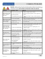
Page 31: ...n the wash cycle 1 Machine is in Delime mode 2 Timer motor is faulty 3 Cam timer jammed by obstruction 1 Flip mode switch to AUTO 2 Verify that the timer is rotating If not check to see that the motor is receiving power If so replace the motor and or timer assembly 3 Remove obstruction Wash or rinse heater does not work 1 Faulty heater element 2 Faulty heater contactor 3 Misadjusted faulty thermos...

Page 32: ... done 2 Remove the obstruction 3 Adjust the frame to accommodate the doors Water leaks at the wash pump 1 Wash pump seal defective 2 Petcock or pump drain if equipped not shut tight 3 Loose hoses hose clamps on the wash pump 1 Replace the seal 2 Close or tighten Tighten the hose clamps Will not rinse during autocycle 1 Defective rinse solenoid 2 Faulty timer 3 No water to the machine 1 Repair or r...

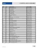
Page 33: ...07610 003 61 42 U 26 17 18 6 20 8 2 7 6 6 6 5 32 16 6 6 23 24 4 4 6 6 31 37 39 CONTROL BOX ASSEMBLY PARTS ...

Page 34: ...27 07610 003 61 42 U CONTROL BOX ASSEMBLY PARTS 10 9 13 14 15 12 11 27 41 42 40 25 21 21 21 22 22 ...

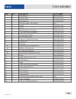
Page 35: ...07610 003 61 42 U 28 26 1 29 28 30 33 34 36 CONTROL BOX ASSEMBLY PARTS ...

Page 36: ... 13 1 Light Yellow 05945 111 44 44 14 1 Decal Wash 150 F Min 09905 002 97 61 15 1 Decal Rinse 180 F Min 09905 002 97 62 16 1 Ground Lug 05940 200 76 00 17 1 Bracket Liquid Level Control Board 05700 002 13 22 18 1 Liquid Level Control Board 06680 200 08 21 19 6 Tricnut 6 32 05340 118 04 00 20 3 Screw 6 32 x 5 8 05305 011 39 85 21 3 Plug 1 2 05975 011 47 81 22 2 Grommet 7 8 Split 05975 200 40 00 23 ...

Page 37: ... Screw 6 32 x 3 8 with Tooth Washer 05305 002 25 91 36 1 Decal Dispenser Connection 09905 003 34 09 37 1 Kit Universal Timer with Bracket 06401 003 80 83 Universal Timer Fused 05945 003 75 23 38 4 Locknut 10 32 05310 373 02 00 39 4 Screw 10 32 x 1 05305 002 19 42 40 1 Switch Rotary Selector 05930 003 97 61 41 1 Switch Operation 05930 301 53 00 42 1 Switch Power 05930 011 49 55 CONTROL BOX ASSEMBLY...

Page 38: ...r NB 05700 002 29 79 1 Hood Weldment Tempstar Ventless 05700 004 19 85 1 Hood Weldment Tempstar S 05700 002 41 36 2 2 Hood Support 05700 002 78 99 3 6 Bolt 1 4 20 x 1 2 05305 274 21 00 4 6 Washer Flat SS 1 4 20 05311 174 01 00 5 4 Spacer Sleeve Hood 05700 003 55 15 6 6 Locknut 1 4 20 with Nylon Insert Not Shown 05310 374 01 00 5 ...

Page 39: ...07610 003 61 42 U 32 14 11 12 10 1 2 3 4 5 6 7 8 16 15 18 24 18 17 11 12 19 20 11 12 19 22 18 23 3d 3c 3f 3b 3a 3e CANTILEVER ARM DOOR ASSEMBLIES PARTS 26 ...

Page 40: ...76 01 00 9 2 Connector Cantilever Arm 05700 011 90 99 10 2 Screw 1 4 20 x 1 1 2 05305 274 23 00 11 4 Washer 1 4 05311 174 01 00 12 4 Locknut 1 4 20 Hex with Nylon Insert Low Profile 05310 374 02 00 13 2 Sleeve Cantilever Arm 05700 000 85 69 14 2 Plug Cantilever Arm 05340 011 35 00 15 1 Magnet Reed Switch 05930 111 51 68 16 2 Locknut 8 32 Hex with Nylon Insert 05310 272 02 00 17 1 Door Right Side C...

Page 41: ... 05700 004 24 32 1 Door Only Left Side 05700 002 29 86 1 Door Only Left Side Ventless 05700 004 24 34 25 1 Door Connecting Plate Not Shown 05700 002 20 78 26 1 Bracket Cantilever Arm Support 09515 003 15 64 27 1 Wear Button 1 2 Dia UHMW Not Shown 05700 011 88 01 28 1 Door Interlock Bracket Not Shown 05700 004 23 17 CANTILEVER ARM DOOR ASSEMBLIES PARTS ...

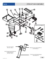
Page 42: ... 27 28 24 25 22 23 21 4 20 19 18 16 16 17 3 1 2 3 5 6 7 8 Bracket Motor Support Weldment 05700 002 68 31 Pump Support Adjustable Bracket 05700 002 20 41 Nut 1 4 20 Hex Nut 05310 011 66 49 Pump Support Adjustable Bracket Complete Assembly 05700 011 60 33 SOLID STATE THERMOSTAT 38 39 40 42 41 ...

Page 43: ... 1 Standpipe 05700 001 25 69 13a 1 Support Ball Stop Lift Not Shown 05700 002 91 55 13b 1 Ball Stop Lift Not Shown 05700 002 91 54 14 1 Overflow Support Bracket 05700 001 27 55 14a 1 Shim Overflow Support Not Shown 05700 002 96 48 15 1 O ring 05330 400 05 00 16 2 Clamp Hose 1 5 16 to 2 1 4 04730 719 01 37 17 1 Discharge Hose 05700 011 88 24 18 1 Nipple 05700 021 34 84 19 1 Pump Support Bracket Ass...

Page 44: ...5700 011 81 64 34 1 Wash Heater Gasket 05330 011 47 79 35 1 Thermostat Regulating 05930 510 02 79 1 Kit Wash Thermostat Replacement Includes thermostat brass fitting two jumper wires instructions 06401 003 18 22 36 1 Thermostat High Limit 05930 004 33 12 37 1 Fitting 1 4 Imperial Brass 05310 924 02 05 38 1 Probe Thermistor 4 06685 004 17 26 39 1 Thermostat Mounting Bracket 05700 004 22 17 40 1 The...

Page 45: ... 17 3 1 2 3 5 6 7 8 26 30 Bracket Motor Support Weldment 05700 002 68 31 Pump Support Adjustable Bracket 05700 002 20 41 Nut 1 4 20 Hex Nut 05310 011 66 49 Pump Support Adjustable Bracket Complete Assembly 05700 011 60 33 SOLID STATE THERMOSTAT 31 32 33 35 34 STEAM TUB ASSEMBLY PARTS ...

Page 46: ... with Nylon Insert 05310 374 02 00 12 1 Scrap Screen 05700 003 07 76 13 1 Standpipe 05700 001 25 69 13a 1 Support Ball Stop Lift Not Shown 05700 002 91 55 13b 1 Ball Stop Lift Not Shown 05700 002 91 54 14 1 Overflow Support Bracket 05700 001 27 55 14a 1 Shim Overflow Support Not Shown 05700 002 96 48 15 1 O ring 05330 400 05 00 16 2 Clamp Hose 1 5 16 to 2 1 4 04730 719 01 37 17 1 Discharge Hose 05...

Page 47: ...401 003 18 67 27 1 Cover Wash Heater 05700 031 47 57 28 1 Decal Warning Disconnect Power 09905 004 08 16 29 2 Locknut 10 24 with Nylon Insert 05310 373 01 00 30 1 Steam Coil 05700 031 41 37 31 1 Probe Thermistor 4 06685 004 17 26 32 1 Thermostat Mounting Bracket 05700 004 22 17 33 1 Thermostat Elan Electric Dual 06685 004 17 27 34 1 Harness 5 Connector 05700 004 23 78 35 1 Harness 4 Connector 0570...

Page 48: ...ART NUMBER 1 4 Bolt 1 4 20 x 1 2 05305 274 02 00 2 4 Locknut 1 4 20 Hex with Nylon Insert 05310 374 02 00 3 1 Front Panel 05700 002 36 65 4 1 Frame Weldment 05700 031 48 01 5 4 Bullet Foot 05340 108 01 03 6 4 Flanged Bullet Foot Optional 05340 002 34 86 2 1 3 4 5 6 ...

Page 49: ...6 18 05310 275 01 00 7 4 Locknut 1 4 20 with Nylon Insert 05310 374 01 00 8 4 Washer 1 4 Flat 05311 174 01 00 9 1 Thermostat Rinse 05930 510 03 79 1 Kit Rinse Thermostat Replacement Includes thermostat brass fitting two jumper wires instructions 06401 011 66 55 10 6 Washer 5 16 05311 275 01 00 11 1 Gasket Rinse Heater 05330 200 02 70 12 1 Fitting 1 4 Imperial Brass 05310 924 02 05 13 1 Probe Therm...

Page 50: ... 09905 004 08 16 5 1 Booster Tank Cover Weldment 05700 001 29 30 6 6 Nut Hex 5 16 18 05310 275 01 00 7 4 Locknut 1 4 20 with Nylon Insert 05310 374 01 00 8 4 Washer 1 4 Flat 05311 174 01 00 9 1 Thermostat Rinse 05930 510 03 79 1 Kit Rinse Thermostat Replacement Includes thermostat brass fitting two jumper wires instructions 06401 011 66 55 10 6 Washer 5 16 05311 275 01 00 11 1 Gasket Rinse Heater ...

Page 51: ...and C Steam Coil Support 05700 002 08 52 3 1 Stand D Steam Coil Support 05700 002 08 53 4 4 Gasket Steam Coil 05700 001 17 86 5 2 Washer Steam Coil 05700 001 17 87 6 2 Adapter Steam Coil Nut 05310 011 17 85 7 1 Stand A Steam Coil Support 05700 002 08 50 8 1 Stand B Steam Coil Support 05700 002 08 51 1 3 4 5 6 7 8 2 COIL ASSEMBLY PARTS TempStar S ...

Page 52: ...s take care not to damage the threads of each individual item Damaged threads can cause leaks and loss of pressure which could adversely affect the performance of the dishmachine It is strongly recommended that thread tape used in conservative amounts be applied to threads when joining components together Do not use thread sealing compounds sometimes referred to as pipe dope Compounds can be eject...

Page 53: ...n 04730 906 10 34 4 4 Nipple Close 3 4 NPT Black Iron 04730 907 01 00 5 1 Gate Valve 3 4 NPT 04820 100 19 00 6 1 Y Strainer 3 4 NPT Black Iron 04730 217 01 32 7 1 Bracket Steam Plumbing Support 05700 002 01 63 8 1 Solenoid Valve Steam Plumbing 220 V 04820 002 01 56 9 1 3 4 NPT Black Iron Pipe 05700 002 20 83 10 1 Elbow 3 4 90 Street 04730 011 87 37 1 2 3 8 7 5 6 4 9 10 STEAM INLET PLUMBING PARTS T...

Page 54: ...various wash motor assemblies a wash motor assembly includes the wash motor and the pump depending on the characteristics of the machine To ensure that you order the correct wash motor assembly for the model you are servicing please refer to the following table Volts Hz Phase Wash Motor Assembly 208 50 1 06105 002 19 87 208 50 3 06105 002 19 87 208 60 1 06105 004 24 80 208 60 3 06105 004 24 80 230...

Page 55: ...3 1 Mechanical Seal 60 Hz 05330 002 34 22 Seal 50 Hz 05330 002 06 21 4 1 Case Capscrew 60 Hz 05305 002 81 88 5 1 Pump Casing 60 Hz 05700 002 85 01 6 1 Shim Kit 60 Hz 05700 002 82 58 7 1 Impeller Assembly 60 Hz 05700 002 81 86 Impeller Assembly 50 Hz 05700 002 41 49 1 7 2 6 5 3 4 Other parts not shown Drain Plug 60 Hz 04730 002 81 89 Bracket 50 Hz 05700 002 06 22 Shaft Adapter 50 Hz 05700 011 95 49...

Page 56: ...00 01 15 04540 121 63 39 Volts Hz Phase Wash Heater 208 50 1 04540 121 47 39 208 50 3 04540 121 47 39 208 60 1 04540 121 47 39 208 60 3 04540 121 47 39 230 50 1 04540 121 47 39 230 50 3 04540 121 47 39 230 60 1 04540 121 47 39 230 60 3 04540 121 47 39 380 50 3 04540 002 44 31 440 50 3 04540 121 65 99 460 60 3 04540 121 65 99 Volts Hz Phase Wash Heater 208 50 1 04540 121 47 39 208 50 3 04540 121 47...

Page 57: ...03 58 27 04540 003 58 28 208 60 1 04540 003 58 27 04540 003 58 28 208 60 3 04540 003 58 27 04540 003 58 28 230 50 1 04540 003 58 27 04540 003 58 28 230 50 3 04540 003 58 27 04540 003 58 28 230 60 1 04540 003 58 27 04540 003 58 28 230 60 3 04540 003 58 27 04540 003 58 28 PARTS HEATERS TempStar with Round Flanged Rinse Heater ...

Page 58: ...omponents take care not to damage the threads of each individual item Damaged threads can cause leaks and loss of pressure which could adversely affect the performance of the dishmachine It is strongly recommended that thread tape used in conservative amounts be applied to threads when joining components together Do not use thread sealing compounds sometimes referred to as pipe dope Compounds can ...

Page 59: ...ss 04730 002 56 27 8 3 Tube Copper 1 2 x 2 1 2 05700 002 17 38 9 2 Tube Copper 1 2 x 37 05700 003 60 80 10 1 Tube Copper 1 2 x 3 05700 001 05 21 11 3 Elbow 1 2 CU x CU 90B 04730 406 01 01 12 2 Tube Copper 1 2 x 2 406 05700 003 60 79 13 1 Tube Copper 1 2 x 3 1 2 05700 003 60 78 14 1 Pressure Gauge 0 100 PSI 06685 111 88 34 15 1 Valve 1 2 208 60 04810 003 71 56 16 1 Vacuum Breaker 1 2 NPT 04820 003 ...

Page 60: ... 1 2 04730 217 01 10 4 1 Ball Valve Bronze 1 4 NPT 04810 011 72 67 5 1 Adapter 1 2 Male CU to MSPS 04730 401 03 01 6 1 Pressure Gauge 0 100 PSI 06685 111 88 34 7 1 Valve Solenoid 1 2 NPT 208 240 V 04810 003 71 56 8 1 Vacuum Breaker 1 2 NPT 04820 003 06 13 9 1 Tube Copper 1 2 x 5 3 4 05700 002 91 03 10 1 Union 1 2 04730 412 05 01 11 1 Elbow 1 2 90 Degree CU to MSPS 04730 406 31 01 7 5 13 11 12 6 12...

Page 61: ...7 00 Nipple 1 2 NPT Close Brass 04730 207 15 00 SHOCK ABSORBER WATER ARRESTOR OPTION Pressure Gauge 0 100 PSI 06685 111 88 34 Ball Valve 1 4 Bronze 04810 011 72 67 Water Pressure Regulator 1 2 NPT 04820 100 04 07 Tee Brass 1 2 x 1 2 x 1 4 NPT 04730 411 25 01 Adapter 1 2 MNPT 04730 011 59 53 PARTS PLUMBING OPTIONS ...

Page 62: ...ION PART NUMBER 1 1 Vacuum Breaker 1 2 Brass 04820 003 06 13 2 1 Elbow 90 Degree 1 2 Street Brass 04730 206 08 00 3 1 Plumbing Rinse Injector 05700 004 19 83 4 1 Plumbing Outlet with Heat Exchanger 05700 004 19 12 5 1 Hose 1 2 ID x 24 LG Red 05700 004 19 89 6 1 Hose 1 2 ID x 60 LG Red 05700 004 19 90 7 1 Hose 1 2 ID x 58 LG Blue 05700 004 19 91 Hose Pac Assembly 05700 004 20 01 TempStar Ventless ...

Page 63: ...27 2 3 Nipple Brass 1 2 x 3 NPT 04730 004 20 10 3 1 Elbow 1 2 NPT 90 Degree Brass 04730 011 42 96 4 1 Tee 1 2 x 1 2 x 1 4 FNPT 04730 002 22 56 5 1 Union 1 2 x 1 2 Brass 04730 003 62 44 6 1 Fitting 1 4 Barb 1 4 MNPT Swivel 04730 011 95 41 7 1 Hose 1 2 ID x 58 Blue 05700 004 19 91 PARTS VENTLESS PLUMBING TempStar Ventless ...

Page 64: ...treet Brass 04730 206 04 34 3 1 Pressure Regulator 3 4 06685 011 58 22 4 1 Nipple 3 4 NPT x 1 3 8 Closed Brass 04730 207 34 00 5 1 Solenoid Valve 220 V 3 4 04810 100 03 18 6 1 Nipple 1 2 Closed Brass 04730 207 15 00 7 1 Elbow 1 2 90 Degree Street Brass 04730 206 08 00 2 2 1 4 5 6 7 3 TempStar Ventless Pressure Regulator comes standard on the Ventless unit ...

Page 65: ... Weldment 1 per machine 05700 002 56 75 Plug 1 8 NPT Brass 3 per Rinse Injector 04730 209 07 37 Rinse Injector Gasket 2 per machine 05330 111 42 81 10 18 15 14 20 13 11 10 10 10 9 17 16 5 7 7 6 10 19 3 2 6 8 9 17 3 1 1 4 2 9 17 FINAL RINSE ARMS MANIFOLD WASH ARMS MANIFOLD 12 21 ...

Page 66: ...700 131 15 07 8 2 Gasket Manifold 05700 111 35 03 9 2 Wash Arm 05700 004 13 13 10 5 Locknut 1 4 20 Hex with Nylon Insert 05310 374 01 00 11 2 Clip Retaining Rinse Head Bushing 05340 112 01 11 12 4 Rinse Arm Washer 05330 011 42 10 13 2 Bushing Rinse Head 05700 021 33 84 14 2 Rinse Arm 05700 003 58 94 15 4 Rinse Arm End cap 04730 111 60 41 16 1 Lower Wash Manifold 05700 031 46 00 17 2 Bearing Assemb...

Page 67: ...07610 003 61 42 U 60 PARTS VENTLESS SYSTEM ASSEMBLY ...

Page 68: ...r 05330 004 18 22 8 1 Gauge 06680 011 86 42 9 1 Coil Box Back 05700 004 18 03 10 12 Bolt 1 4 20 x 3 8 Hex 05305 274 20 00 11 1 Bracket Vacuum Breaker 05700 004 18 91 12 1 Shroud Hear Exchanger 05700 004 18 92 13 6 Nut Lock 10 24 Hex with Nylon Insert 05310 373 01 00 14 6 Washer Flat 05311 173 02 00 15 2 Fan 3 62 Square 85 236 V AC Corrosion Resistant 05999 004 19 46 16 8 Screw 6 32 x 1 1 2 05305 0...

Page 69: ...Rod Interlock Weldment 05700 004 23 15 4 1 Solenoid Horizontal 1 Push 04820 004 24 11 5 1 Spring Compression 05935 004 24 10 6 1 Base Door Interlock Box 05700 004 24 25 7 8 Screw 3 8 Pan Head 05305 171 02 00 8 8 Washer Flat 05311 173 02 00 9 2 Locknut 1 4 20 05310 374 01 00 10 2 Washer 1 4 20 05311 174 01 00 11 1 Fitting 05975 011 59 50 12 2 Connector 2 Conductor 05935 004 03 49 13 1 Cord SJ 55 LG...

Page 70: ...111 47 51 OTHER DOOR INTERLOCK SDI COMPONENTS NOT SHOWN Transformer Mounting Bracket 05700 031 62 82 Exhaust Fan Control 2 Din Rail 05700 002 36 09 415 440 460 V Transformer 05950 111 65 93 380 V Transformer 05950 111 64 17 Exhaust Fan Control Delay Timer 05945 004 22 78 Transformer Mounting Box 05700 002 10 01 Transformer Mounting Box Top Not Shown 05700 000 78 53 2 Amp Circuit Breaker 05925 111 ...

Page 71: ...Reed 05930 111 51 69 16 2 Snap Ring Retaining Rinse Arm 05340 112 01 11 17 1 Bearing Assembly Wash Arm 05700 021 35 97 18 1 Timer Universal 06401 003 80 83 19 4 Washer Rinse Arm 05330 011 42 10 20 1 Vacuum Breaker 1 2 Brass 04820 003 06 13 21 1 Solenoid Valve 1 2 208 240 V 04810 003 71 56 22 1 Drain Seat O ring 05330 400 05 00 23 1 Rotary Selector Switch 05930 003 97 61 24 1 Operation Switch 05930...

Page 72: ...Brass 04730 011 69 93 5 1 Reducer 1 1 2 x 1 4 Hex Brass 04730 002 55 76 6 1 Union 1 4 Modified 05700 001 16 52 7 1 Nipple 1 1 2 Brass 04730 207 40 00 8 1 Tee 1 1 2 Brass 04730 011 69 93 9 1 Elbow 1 1 2 NPT Female 04730 206 32 00 10 1 Nipple 1 2 Brass 04730 207 15 00 11 1 Valve Check 1 2 04820 002 55 77 12 1 Reducer 1 2 x 1 4 Brass 04730 003 62 16 13 1 Solenoid Valve 1 4 240 V 04810 002 31 09 1 13 ...

Page 73: ...700 031 47 57 2 1 Large Fitting 05975 011 65 51 3 1 Conduit Fitting 45 Degree 1 2 05975 011 45 23 4 2 Lock Nut 6 32 Hex 05310 373 03 00 5 1 Thermostat 05930 003 13 65 6 1 Conduit Fitting 90 Degree 1 2 05975 011 45 14 7 1 Small Fitting 05975 011 49 03 8 1 Drain Quench Bracket 05700 004 07 92 1 2 3 4 5 6 7 8 ...

Page 74: ...67 07610 003 61 42 U Connect 1 1 2 drain plumbing elbow can be removed if not needed Connect 1 4 cold water line PARTS DRAIN QUENCH ASSEMBLY ...

Page 75: ...07610 003 61 42 U 68 SCHEMATICS 208 230 V 50 60 HZ 1 PHASE ...

Page 76: ...69 07610 003 61 42 U SCHEMATICS 460 V 50 60 HZ 3 PHASE ...

Page 77: ...07610 003 61 42 U 70 SCHEMATICS LT NB 208 230 V 50 60 HZ 1 PHASE ...

Page 78: ...71 07610 003 61 42 U SCHEMATICS LT NB 460 V 50 60 HZ 3 PHASE ...

Page 79: ...07610 003 61 42 U 72 SCHEMATICS STEAM 208 230 V 50 60 HZ 1 3 PHASE ...

Page 80: ...73 07610 003 61 42 U SCHEMATICS SDI OPTIONS ...

Page 81: ...07610 003 61 42 U 74 SCHEMATICS DRAIN QUENCH OPTION ...

Page 82: ... 2 A 40 F RISE BOOSTER WASH MOTOR 230V 208V 3 4 HP 5 7 A 3 4 HP 5 7 A WASH HEATER 4 1 KW 19 7 A 5 KW 21 7 A RINSE HEATER 10 5 KW 50 4 A 12 9 KW 56 1 A TOTAL LOAD 75 8 A 83 6 A 70 F RISE BOOSTER 208 230 Volt 60 Hz 1 Phase 24 3 A 70 F RISE BOOSTER 4000897 Conforms to UL Std 921 Conforms to CSA Std C22 2 No 168 Intertek TempStar units that are manufactured with the above referenced data plate are abl...

Page 83: ...SER CONNECTION DETERGENT DISPENSER CONNECTION MAXIMUM LOAD 1 AMP 240 120 VAC LIVE WHEN MACHINE POWER SWITCH IS ON LIVE WHEN RINSE VALVE IS OPEN LIVE WHEN WASH PUMP MOTOR IS ON L1 OUT L2 OUT FUSE 3 AMP SLOW ACTING L1 OUT L2 OUT FUSE 3 AMP SLOW ACTING L1 OUT L2 OUT FUSE 3 AMP SLOW ACTING Do NOT connect primary load directly to Fuse Block CAUTION NOTICE Orientation of Fuse Block and wires might diffe...

Page 84: ...TempStar Manual 07610 003 61 42 U Jackson WWS Inc 6209 N US Hwy 25E Gray KY 40734 USA 1 888 800 5672 www jacksonwws com ...

Reviews: