background image

MANUFACTURERS WARRANTY

ONE YEAR LIMITED PARTS & LABOR WARRANTY

ALL NEW JACKSON DISHWASHERS ARE WARRANTED TO THE ORIGINAL PURCHASER TO BE FREE FROM DEFECTS IN 
MATERIAL OR WORKMANSHIP, UNDER NORMAL USE AND OPERATION FOR A PERIOD OF (1) ONE YEAR FROM DATE OF 
PURCHASE, BUT IN NO EVENT TO EXCEED (18) EIGHTEEN MONTHS FROM DATE OF SHIPMENT FROM THE FACTORY.

Jackson WWS agrees under this warranty to repair or replace, at its discretion, any original part which fails under normal use due to faulty 

material or workmanship during the warranty period, providing the equipment has been unaltered, and has been properly installed, maintained 

and operated in accordance with applicable factory instruction manual furnished with the machine and failure is reported to the authorized 

service agency within the warranty period. This includes the use of factory specified genuine replacement parts, purchased directly from a Jackson 

authorized parts distributor or service agency. Use of generic replacement parts may create a hazard and void warranty certification.

The labor to repair or replace such failed part will be paid by Jackson WWS, within the continental United States, Hawaii and Canada, during the 

warranty period provided a Jackson WWS authorized service agency, or those having prior authorization from the factory, performs the service. 

Any repair work by persons other than Jackson WWS authorized service agency is the sole responsibility of the customer. Labor coverage is limited 

to regular hourly rates; overtime premiums and emergency service charges will not be paid by Jackson WWS.

Accessory components not installed by the factory carry a (1) one year parts warranty only. Accessory components such as table limit switches, 

pressure regulators, pre-rinse units, etc. that are shipped with the unit and installed at the site are included. Labor to repair or replace these 

components is not covered by Jackson WWS.

This warranty is void if failure is a direct result from shipping, handling, fire, water, accident, misuse, acts of God, attempted repair by authorized persons, 

improper installation, if serial number has been removed or altered, or if unit is used for purpose other than originally intended.

TRAVEL LIMITATIONS

Jackson WWS limits warranty travel time to (2) two hours and mileage to (100) one hundred miles. Jackson WWS will not pay for travel time 

and mileage that exceeds this, or any fees such as those for air or boat travel without prior authorization.

WARRANTY REGISTRATION

To register your product go to www.jacksonwws.com or call 1-888-800-5672. Failure to register your product will void the warranty.

REPLACEMENT PARTS WARRANTY

Jackson replacement parts are warranted for a period of 90 days from date of installation or 180 days from the date of shipment from the factory, 

whichever occurs first.

PRODUCT CHANGES AND UPDATES

Jackson WWS reserves the right to make changes in design and specification of any equipment as engineering or necessity requires.

THIS IS THE ENTIRE AND ONLY WARRANTY OF JACKSON WWS. JACKSON’S LIABILITY ON ANY CLAIM OF ANY KIND, 

INCLUDING NEGLIGENCE, WITH RESPECT TO THE GOODS OR SERVICES COVERED HEREUNDER, SHALL IN NO CASE 

EXCEED THE PRICE OF THE GOODS OR SERVICES OR PART THEREOF WHICH GIVES RISE TO THE CLAIM.

THERE ARE NO WARRANTIES, EXPRESSED OR IMPLIED, INCLUDING FOR FITNESS OR MERCHANTABILITY, THAT ARE NOT 

SET FORTH HEREIN, OR THAT EXTEND BEYOND THE DURATION HEREOF. UNDER NO CIRCUMSTANCES WILL JACKSON 

WWS BE LIABLE FOR ANY LOSS OR DAMAGE, DIRECT OR CONSEQUENTIAL, OR FOR THE DAMAGES IN THE NATURE OF 

PENALTIES, ARISING OUT OF THE USE OR INABILITY TO USE ANY OF ITS PRODUCTS. 

ITEMS NOT COVERED

THIS WARRANTY DOES NOT COVER CLEANING OR DELIMING OF THE UNIT OR ANY COMPONENT SUCH AS, BUT NOT 

LIMITED TO, WASH ARMS, RINSE ARMS OR STRAINERS AT ANYTIME. NOR DOES IT COVER ADJUSTMENTS SUCH AS, BUT 

NOT LIMITED TO TIMER CAMS, THERMOSTATS OR DOORS, BEYOND 30 DAYS FROM THE DATE OF  INSTALLATION. IN 

ADDITION, THE WARRANTY WILL ONLY COVER REPLACEMENT WEAR ITEMS SUCH AS CURTAINS, DRAIN BALLS, DOOR 

GUIDES OR GASKETS DURING THE FIRST 30 DAYS AFTER INSTALLATION. ALSO, NOT COVERED ARE CONDITIONS CAUSED 

BY THE USE OF INCORRECT (NON-COMMERICAL) GRADE DETERGENTS, INCORRECT WATER TEMPERATURE OR PRES

-

SURE, OR HARD WATER CONDITIONS.

i

Summary of Contents for TempStar Series

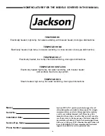
Page 1: ...MESTIC UNITS ELECTRICALLY HEATED MODELS TEMPSTAR HH TEMPSTAR HH NB TEMPSTAR HH LT TEMPSTAR HH VENTLESS STEAM HEATED MODELS TEMPSTAR HH S Jackson WWS Inc P O Box 1060 Barbourville KY USA 1 888 800 5672...

Page 2: ......

Page 3: ...d attempted repair by authorized persons improper installation if serial number has been removed or altered or if unit is used for purpose other than originally intended TRAVEL LIMITATIONS Jackson WWS...

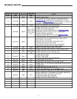
Page 4: ...trol Box dimensions hood weldment control box schematics Corrected the rinse tank cover number updated the cantilever support bracket reed switch numbers K 10 08 08 ARL 7990 Added hi limit thermostat...

Page 5: ...STAR HH S Steam heated high temp hot water sanitizing door type dishmachine Model Serial No Installation Date Service Rep Name Phone Number Jackson WWS INC provides technical support for all of the di...

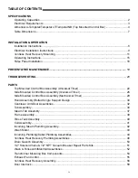
Page 6: ...Mounted Control Box Assembly Universal Timer 26 Side Mounted Control Box Assembly Mechanical Timer 29 Hood Assembly Bolted Single Support Design 30 Cantilever Arm Door Assemblies 32 Tub Assembly 34 St...

Page 7: ...Tempstar HH Universal Timer 460V 60Hz Three Phase 63 Tempstar HH S Universal Timer 208 230V 50 60Hz Single Three Phase 64 Tempstar HH 208 230V 50 60Hz Single Three Phase 65 Tempstar HH 460V 60Hz Thre...

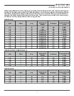
Page 8: ...HH Ventless Wash Temperature minimum F 150 Wash Temperature minimum C 66 Rinse Temperature minimum F 180 Rinse Temperature minimum C 83 Inlet Water Temperature 12kW Rinse Heater F 140 12kW Rinse Heate...

Page 9: ...l Amps Typical Electrical Circuit 415 3 60 12kW 28A 35AMP 415 3 60 14kW 30A 40AMP 208 1 60 12kW 240V 75A 100AMP 208 1 60 12kW 240V 82A 110AMP 230 1 60 12kW 240V 81A 110AMP 230 1 60 14kW 240V 90A 125AM...

Page 10: ...34 861mm 27 686mm 25 1 4 641mm 3 76mm 1 25mm 11 3 4 298mm 15 1 4 387mm 73 1856mm 86 3 4 2203mm 17 432mm 3 76mm 4 102mm 4 102mm A A B B B C LEGEND A Drain 1 1 2 IPS B Water Inlet 3 4 IPS C Electrical...

Page 11: ...25 637mm 251 4 639mm B 1 A 3 76mm 4 101mm 4 102m 3 77mm 151 4 388m 861 4 2190mm LEGEND A DRAIN 1 1 2 IPS B WATER INLET 3 4 IPS C ELECTRICAL CONNECTION All dimensions are in inches All vertical dimens...

Page 12: ...25 1 4 639mm 86 1 4 2156mm 1 25mm 7 1 2 190mm 12 3 4 327mm 12 1 4 310mm 4 102mm 4 102mm 34 863mm 27 687 3 76mm 15 1 4 388mm 4 102mm B A A C B LEGEND A Drain 1 1 2 B Water Inlet 3 4 C Electrical Conne...

Page 13: ...88 2235mm A C 4 101mm 3 76mm 51 4 134mm B WATER INLET 3 4 MIP C ELECTRICAL CONNECTIONS All vertical dimensions are 1 2 due to adjustable bullet feet B A 88 223 251 4 639mm 23 4 79mm 4 101mm 51 4 134m...

Page 14: ...A B A C OPENING D C G F ROLL A B D C OPENING D LETTER DIM IN DIM CM A 4 MIN 10 2 CM MIN B 2 1 2 6 4 CM C 20 1 2 52 1 CM D 25 1 4 64 1 CM E 2 1 4 10 2 CM F 1 1 2 3 8 CM G 3 4 1 9 CM TABLE DIMENSIONS C...

Page 15: ...gned to operate while level This is important to prevent any damage to the machine during operation and to ensure the best results possible The unit comes equipped with adjustable bullet feet which ca...

Page 16: ...connections must comply with the applicable portions of the National Electrical Code ANSI NFPA 70 latest edition and or other electrical codes Disconnect electrical power supply and place a tag at the...

Page 17: ...TALLATION OPERATION Due to shipping constraints the Tempstar High Hood is shipped dissembled you should receive two pieces 2 1 Heat Recovery Unit Base Unit Fully Assembled Unit The heat recovery unit...

Page 18: ...r air inlet Upper unit should slide inside the lower air inlet at the seam Locate and remove the four 1 4 20 bolts using a 7 16 wrench These are located in top left and right corner of the unit 3 Rein...

Page 19: ...two hoses using an adustable wrench The hoses are cut to length and will only reach their intended connection point A Connect the Gauge B Final Rinse Inlet C PRV Inlet from Coil D Booster Outlet Befor...

Page 20: ...te the wire connectors at the top of the unit and connect the white and black wires from the base unit Slide wire into the hole and push the lever down Tidy up the wires and lock them in place with th...

Page 21: ...side down in racks so that they do not hold water during the cycle Load plates and saucers in the same direction with the food surface facing the unload end of the machine DAILY MACHINE PREPARATION Re...

Page 22: ...to clean out the inside of the arms If the nozzles appear to be clogged use a toothpick to remove the obstruction Wipe the inside of the unit removing all soil and scraps Reassemble the wash and rins...

Page 23: ...nd detergent vendor to discuss a complete training program for operators 5 Certain dishmachine models require that chemicals be provided for proper operation and sanitization Some models may require t...

Page 24: ...panel against the side of the dishmachine and push upward 5 The panel will clip in at the top inside of the unit 6 The holes in the false panel will line up with the rack assembly holes 7 Reinstall th...

Page 25: ...clean strainers wipe them out with a rag and rinse under a faucet For stubborn debris a toothpick can be used to dislodge any obstructions from the perforations Do not beat strainers on waste cans onc...

Page 26: ...correct replace the switch Clean probe if fouled If clean and not working replace Dishmachine will not fill after the door is closed Power ON light is not illuminated Service breaker tripped Machine...

Page 27: ...s Water leaks at the wash pump Wash pump seal defective Petcock or pump drain if equipped not shut tight Loose hoses hose clamps on the wash pump Replace the seal Close or tighten Tighten the hose cla...

Page 28: ...PARTS 22 TOP MOUNTED CONTROL BOX ASSEMBLY 30 28 29 25 22 21 26 33 34 36 1...

Page 29: ...23 PARTS 13 9 10 42 40 41 12 15 11 14 27 8 39 37 6 2 6 7 6 5 32 16 31 6 6 6 4 23 24 6 20 18 17 TOP MOUNTED CONTROL BOX ASSEMBLY CONTINUED...

Page 30: ...cal Wash 150 F Min 09905 002 97 61 15 1 Decal Rinse 180 F Min 09905 002 97 62 16 1 Ground Lug 05940 200 76 00 17 1 Bracket Liquid Level Control Board 05700 002 13 22 18 1 Liquid Level Control Board 06...

Page 31: ...003 75 23 38 4 Locknut 10 32 05310 373 02 00 39 4 Screw 10 32 x 1 05305 002 19 42 40 1 Switch Rotary Selector 05930 003 97 61 41 1 Switch Operation 05930 301 53 00 42 1 Switch Power 05930 011 49 55 43...

Page 32: ...PARTS SIDE MOUNT UNIVERSAL TIMER CONTROL BOX ASSEMBLY 26 1 3 2 9 12 13 30 36 27 28 29 1 26 31 10 32 5 7 10 10 4 15 22 24 21 20 19 23 11 21 18 24 14...

Page 33: ...02 82 46 10 1 Relay 240V 50 60Hz Top Mount 05945 002 47 74 11 8 Screw 6 32 x 3 8 SEMS with External Tooth Washer 05305 002 25 91 12 1 Decal Control Box Gauge 09905 002 10 69 13 1 Thermometer 96 Lead R...

Page 34: ...LT 05930 003 97 61 28 1 Switch Operation 05930 301 53 00 29 1 Decal Control Box Cover 09905 003 97 39 1 Decal Control Box Cover LT ONLY not shown 09905 004 22 33 30 1 Light Red 05945 504 07 18 31 1 Li...

Page 35: ...002 82 46 4 1 Relay 240V 50 60Hz Top Mount 05945 002 47 74 5 1 Timer Cam Mechanical 05945 303 31 00 6 1 Contactor 2 Pole 220V 20 Amp 208 230V Unit only 05945 002 74 20 7 4 Bolt 10 32 x 1 2 Slotted Tr...

Page 36: ...PARTS HOOD ASSEMBLY 30 1 5 4 2 3 6 7 10 8 9...

Page 37: ...uide 05700 031 76 34 4 1 Right Back Outer Door Guide 05700 031 76 32 5 1 Right Back Inner Door Guide 05700 031 76 35 6 1 Left Back Outer Door Guide 05700 031 76 33 7 34 Locknut 1 4 20 Hex w Nylon Inse...

Page 38: ...ylon Insert 05310 374 02 00 6 4 Plug Cantilever 05340 011 35 00 7 2 Connecting Link 05700 021 92 45 8 2 Spring Pin 1 4 x 1 1 8 Long 05315 407 06 00 9 2 Yoke Assembly 05700 000 75 77 10 2 Nut 3 8 16 S...

Page 39: ...ew 1 4 20 x 5 8 05305 274 24 00 24 12 Locknut 1 4 20 S S Hex with Nylon Insert 05310 374 01 00 25 2 Screw 1 4 20 x 1 2 Long Hex Head 05305 274 02 00 26 2 Spacer PB Bolt 05700 000 29 40 27 2 Bracket Do...

Page 40: ...27 28 37 34 36 35 26 33 1 29 17 16 18 19 20 Solid State Thermostat 15 14 11 38 39 40 LOCKNUT 1 4 20 05310 374 01 00 W BRACKET MOTOR MOUNT INNER 05700 004 13 09 F BRACKET MOTOR MOUNT OUTER 05700 004 13...

Page 41: ...91 55 1 Ball Stop Lift 05700 002 91 54 1 Shim Overflow Support 05700 002 96 48 14 1 Overflow Support Bracket 05700 001 27 55 15 1 O Ring 05330 400 05 00 16 2 Clamp Hose 1 5 16 to 2 1 4 04730 719 01 37...

Page 42: ...ct Power 09905 100 75 93 32 1 Decal High Limit 09905 011 84 32 33 1 Thermostat Bracket 05700 011 81 64 34 1 Wash Heater Gasket 05330 011 47 79 35 1 Thermostat Regulating 05930 510 02 79 1 Kit Wash The...

Page 43: ...002 68 31 Pump Support Adjustable Bracket 05700 002 20 41 Represents an item not shown Solid State Thermostat 31 32 33 LOCKNUT 1 4 20 05310 374 01 00 W BRACKET MOTOR MOUNT INNER 05700 004 13 09 F BRA...

Page 44: ...6 to 2 1 4 04730 719 01 37 17 1 Discharge Hose 05700 011 88 24 18 1 Nipple 05700 021 34 84 19 1 Pump Support Bracket Assembly 05700 002 00 46 20 1 Clamp Hose 5 5 8 to 6 04730 011 34 90 21 1 Connector...

Page 45: ...SEMBLY Cover Front Panel 05700 002 01 42 Frame Weldment 05700 002 03 49 Frame Weldment 415V 05700 002 62 41 Frame Weldment 05700 004 22 56 Bullet Foot 05340 108 02 06 Bullet Foot 05340 002 14 55 Flang...

Page 46: ...Thermostat High Limit 05930 011 49 43 8 1 Thermostat Regulating with Imperial Brass Fitting 06401 011 66 55 9 6 Lockwasher 5 16 Split 05311 275 01 00 10 1 Gasket Rinse Heater 05330 200 02 70 11 4 Lock...

Page 47: ...team Coil Support 05700 002 08 53 Stand B Steam Coil Support 05700 002 08 51 Adapter Steam Coil Nut 2 per assembly 05310 011 17 85 Washer Steam Coil 2 per assembly 05700 001 17 87 Gasket Steam Coil 4...

Page 48: ...sembly 04730 907 01 00 Bushing Reducing 3 4 to 1 2 04730 911 02 34 Bushing Reducing 3 4 to 1 2 04730 911 02 34 Union 3 4 NPT Black Iron 2 per assembly 04730 912 01 01 3 4 NPT Black Iron Pipe 05700 002...

Page 49: ...emoved from the motor you are installing contact Jackson technical support immediately The Tempstar models covered in this manual come supplied with various heaters depending on the characteristics of...

Page 50: ...PARTS INCOMING OUTLET PLUMBING ASSEMBLIES INCOMING PLUMBING OUTLET PLUMBING 15 4 9 10 16 1 7 3 2 6 5 4 4 8 9 10 11 13 12 10 17 13 9 18 13 14 12 10 44...

Page 51: ...0 011 58 28 15 1 Vacuum Breaker 3 4 NPT 04820 002 53 77 16 1 Tube Copper 3 4 x 44 3 8 Long 05700 002 25 05 17 1 Elbow 3 4 90 Copper to FSPS Brass 04730 406 41 01 18 1 Elbow 3 4 90 Copper to Copper Str...

Page 52: ...1 Nipple Brass 3 4 NPT x 3 Long 04730 011 38 29 4 1 Union 3 4 NPT Brass with O Ring 05700 002 63 79 5 3 Nipple Close Brass 3 4 NPT 04730 207 34 00 6 1 Valve Solenoid 3 4 NPT 04810 100 03 18 7 1 Tee B...

Page 53: ...1 2 MNPT X CU Male 04730 011 59 53 3 1 Strainer Y 1 2 04730 217 01 10 4 1 Vale Ball Test Cock 1 4 Bronze 04810 011 72 67 5 1 Adapter Male 04730 401 03 01 6 1 Gauge 0 100 Pressure 06685 111 88 34 7 Vac...

Page 54: ...22 73 2 1 4 5 6 7 3 HOSE PAC ASSEMBLY TEMPSTAR 05700 004 20 01 HOSE PAC ASSEMBLY TEMPSTAR HH 05700 004 20 02 05700 004 19 89 OSE 1 2 ID X 24 LG RED 05700 004 19 99 OSE 1 2 ID X 67 LG RED 05700 004 20...

Page 55: ...5 1 Union 1 2 X 1 2 Brass 04730 003 62 44 6 1 Fitting 1 4 Barb 1 4 MNPT Swivel 04730 011 95 41 1 2 3 2 4 2 5 6 1 2 2 3 4 5 6 7 ITEM QTY DESCRIPTION PART NUMBER 1 1 Bushing Hex 3 4 M to 1 2 Brass 0473...

Page 56: ...shmachine Drain Nipple 1 1 2 NPT 04730 207 40 00 Elbow 1 1 2 90 Street 04730 206 32 00 Drain Quench Assembly 06401 002 59 52 PARTS DRAIN QUENCH ASSEMBLY From the existing drain attach two additional T...

Page 57: ...ve Body Complete 240 Volt Solenoid Valve Assembly 04810 100 03 18 Coil Housing only 06401 003 07 44 Complete Vacuum Breaker Assembly 04820 002 53 77 Components of Repair Kit 06401 003 06 24 Cap Screw...

Page 58: ...13 16 19 14 11 12 15 15 2 3 4 5 7 17 8 6 18 18 18 18 18 2 3 19 5 21 9 18 1 PARTS WASH RINSE ARM MANIFOLD ASSEMBLIES 52 7 21 17 10 1 5 9...

Page 59: ...Arm Assembly 415V not shown 05700 021 63 81 1 Wash Arm Weldment 415V 05700 021 63 42 1 Bearing Assembly 415V 05700 021 63 80 2 Rinse Arm Assembly 05700 002 58 09 11 2 Clip Retaining Rinse Head Bushing...

Page 60: ...PARTS 460 VOLT MACHINE TRANSFORMER MOUNTING BOX 54...

Page 61: ...PARTS PARTS 55 EXHAUST FAN CONTROL OPTION...

Page 62: ...PARTS TEMPSTAR HH VENTLESS HEAT REVOCERY SYSTEM ASSEMBLY 1 2 3 15 16 4 10 9 5 11 8 12 7 17 6 56...

Page 63: ...05700 004 18 04 7 1 Gasket Heat Exchanger 05330 004 18 22 8 1 Gauge 06680 011 86 42 9 1 Coil Box Back 05700 004 18 03 10 12 Bolt 1 4 20 X 3 8 Hex 05305 274 20 00 11 1 Bracket Vacuum Breaker 05700 004...

Page 64: ...dment 05700 004 23 15 4 1 Soleniod Horizontal 1 Push 04820 004 24 11 5 1 Spring Comp 05935 004 24 10 6 1 W Base Door Interlock Box 05700 004 24 25 7 8 Screw 3 8 Pan Head 05305 171 02 00 8 8 Washer Fla...

Page 65: ...5 111 47 51 Latch access hole The following instructions are for Tempstar HH models equipped with the Safety Door Interlock option These instructions should only be used if the door interlock fails to...

Page 66: ...ELECTRICAL SCHEMATICS SOLID STATE TEMPSTAR HH TOP MOUNT CONTROLS 208 230V 60HZ 1 3 PHASE 60...

Page 67: ...ELECTRICAL SCHEMATICS 61 TEMPSTAR HH UNIVERSAL TIMER 208 230V 60HZ 1 3 PHASE...

Page 68: ...ELECTRICAL SCHEMATICS 62 SOLID STATE TEMPSTAR HH TOP MOUNT W CYCLE SWITCHES 460V 60HZ 3 PHASE...

Page 69: ...ELECTRICAL SCHEMATICS TEMPSTAR HH UNIVERSAL TIMER 460V 60HZ 3 PHASE 63...

Page 70: ...ELECTRICAL SCHEMATICS TEMPSTAR HH S UNIVERSAL TIMER 208 230V 60HZ 1 3 PHASE 64...

Page 71: ...ELECTRICAL SCHEMATICS TEMPSTAR HH 208 230V 60HZ 1 3 PHASE 65...

Page 72: ...ELECTRICAL SCHEMATICS TEMPSTAR HH 460V 60HZ 3 PHASE 66...

Page 73: ...ELECTRICAL SCHEMATICS TEMPSTAR HH S 208 230V 60HZ 1 3 PHASE 67...

Page 74: ...ELECTRICAL SCHEMATICS TEMPSTAR HH NB 208V 230V 50 60HZ 1 PHASE 68...

Page 75: ...ELECTRICAL SCHEMATICS TEMPSTAR HH NB LT 208V 230V 50 60HZ 1 PHASE 69...

Page 76: ...70 ELECTRICAL SCHEMATICS OPTIONS SDI OPTION...

Page 77: ...ELECTRICAL SCHEMATICS OPTIONS EXHAUST FAN HOOKUP DRAIN QUENCH OPTIONS 71...

Page 78: ...Tempstar HH Series Installation Operation Technical Manual 07610 002 23 32 Issued 09 14 07...

Reviews: