8
07610-003-61-42-T
INSTRUCTIONS
INSTALLATION
Before installing the unit, check the container and machine for damage. A damaged
container is an indicator that there may be some damage to the machine. If there is
damage to both the container and machine, do not throw away the container. The
dishmachine has been inspected and packed at the factory and is expected to arrive
to you in new, in undamaged condition. However, rough handling by carriers or others
may result in there being damage to the unit while in transit. If such a situation occurs,
do not return the unit to Jackson; instead, contact the carrier and ask them to send a
representative to the site to inspect the damage to the unit and to complete an inspection
report. You must contact the carrier within 48 hours of receiving the machine. Also,
contact the dealer that sold you the unit.
Once the machine has been removed from the container, ensure that there are no
missing parts from the machine. This may not be obvious at fi rst. If it is discovered that
an item is missing, contact Jackson immediately to have the missing item shipped to
you.
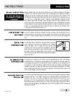
The dishmachine is designed to operate while being level.
This is important to prevent any damage to the machine
during operation and to ensure the best results when
washing ware. The unit comes with adjustable bullet feet,
which can be turned using a pair of channel locks or by
hand if the unit can be raised safely. Ensure that the unit is
level from side to side and from front to back before making
any connections.
All plumbing connections must comply with all applicable local, state, and national
plumbing codes. The plumber is responsible for ensuring that the incoming water line
is thoroughly fl ushed prior to connecting it to any component of the dishmachine. It
is necessary to remove all foreign debris from the water line that may potentially get
trapped in the valves or cause an obstruction. Any valves that are fouled as a result of
foreign matter left in the water line, and any expenses resulting from this fouling, are
not the responsibility of the manufacturer.
The drain for the Tempstar models covered in this manual are gravity discharge drains.
All piping from the 1 1/2” FNPT connection on the wash tank must be pitched (1/4”
per foot) to the fl oor or sink drain. All piping from the machine to the drain must be a
minimum 1 1/2” I.P.S. and shall not be reduced. There must also be an air gap between
the machine drain line and the fl oor sink or drain. If a grease trap is required by code, it
should have a fl ow capacity of 5 gallons per minute. Units equipped with Drain Quench
Option,see page 60.
VISUAL INSPECTION
DO NOT THROW AWAY
CONTAINER IF DAMAGE
IS EVIDENT!
LEVEL THE
DISHMACHINE
UNPACKING THE
MACHINE:
PLUMBING THE
DISHMACHINE
CONNECTING THE
DRAIN LINE
Frame with Adjustable Foot
Raise
Lower
Summary of Contents for TEMPSTAR
Page 2: ......
Page 31: ...24 07610 003 61 42 T TOP CONTROL BOX ASSEMBLY PARTS Continued 26 1 29 28 30 33 34 36 ...
Page 66: ...59 07610 003 61 42 T PARTS TEMPSTAR VENTLESS SYSTEM ASSEMBLY ...
Page 77: ...70 TEMPSTAR 460 V 60 HZ 3 PHASE SCHEMATICS TEMPSTAR TOP MOUNT W CYCLE SWITCHES ...
Page 79: ...72 TEMPSTAR LT NB 208 230V 50 60HZ 1 3 PHASE SCHEMATICS TEMPSTAR TOP MOUNT W CYCLE SWITCHES ...
Page 82: ...75 07610 003 61 42 T SCHEMATICS SDI OPTIONS ...
Page 83: ...76 07610 003 61 42 T DRAIN QUENCH OPTIONS SCHEMATICS ...
Page 85: ......


