28
1
2
3
OPERATION
READ MANUAL BEFOR OPERATING.
REPLACEMENT MANUAL AVAILABLE FROM:
TEXTRON TURF CARE AND SPECIALTY
PRODUCTS, RACINE WI.
To Start
To Stop/Park
To Drive/Transport
To Mow
1. Parking Brake.............On
2. Traction Pedal......Neutral
3. Mower Switch.............Off
4. Throttle......................Half
5. Ignition........................On
5. Glow Plug Light.........Off
7. Ignition.....................Start
1. Traction Pedal......Neutral
2. Mower Switch..............Off
3. Parking Brake.............On
4. Throttle.....................Slow
5. Ignition........................Off
6. Remove Key
1. Follow "To Start"
Instructions.
2. Mower Switch.............Off
3. Cutting Units..........Raise
4. Parking Brake.............Off
5. Throttle......................Fast
6. Slowly depress
traction pedal
1. Follow "To Start"
Instructions.
2. Throttle......................Fast
3. Mower Switch...........Mow
4. Parking Brake.............Off
5. Cutting Units.........Lower
6. Slowly depress
traction pedal
LF-3400: Engine Power: 23.0 kW @ 3000 rpm.
Vehicle Mass: 1160 kg (2WD), 1230 kg (4WD)
LF-3800: Engine Power: 26.5 kW @ 3000 rpm.
Vehicle Mass: 1250 kg (2WD), 1320 kg (4WD)
STARTING THE TRACTOR
LAMPS NOT USED: 1,2,8,14,15,17,18,24,26,27,28,29,30,48
LAMP
HAS POWER)
4....INPUT...KEY SWITCH-"START" POST
3....INPUT...PROGRAM ACTIVE (INDICATES CONTROLLER
5....INPUT...NEUTRAL START SWITCH
6....INPUT...BRAKE SWITCH
7....INPUT...SEAT SWITCH
9....INPUT...CRUISE CONTROL SWITCH-OFF-PIN 1
10...INPUT...CRUISE CONTROL SWITCH-ON-PIN 6
11...INPUT...HYDRAULIC OIL LEVEL FLOAT SWITCH
13...INPUT...ENGINE OIL PRESSURE SWITCH
12...INPUT...HYDRAULIC OIL LEVEL ALARM SWITCH-PIN 3
16...INPUT...LIFT LIMIT SWITCH-LEFT WING
19...INPUT...LIFT LIMIT SWITCH-RIGHT WING
20...INPUT...JOYSTICK-LEFT-PIN 4
21...INPUT...JOYSTICK-RIGHT-PIN 5
25...INPUT...DECK SWITCH-FORWARD DIRECTION-PIN 1
37...OUTPUT...DECK SWITCH-LEFT WING ACTIVE SIGNAL-PIN
31...OUTPUT...GLOW PLUG RELAY AND INDICATOR
32...OUTPUT...LIGHT TEST
33...OUTPUT...START RELAY AND INDICATOR
34...OUTPUT...FUEL HOLD COIL
35...OUTPUT...WARNING HORN
36...OUTPUT...HYDRAULIC OIL LEVEL LIGHT
38...OUTPUT...DECK SWITCH-CENTER ACTIVE SIGNAL-PIN 5
40...OUTPUT...CRUISE CONTROL COIL/LIGHT(OPTION)
41...OUTPUT...VALVE-LIFT PRESSURE
42...OUTPUT...VALVE-RAISE-LEFT WING
ALL OTHER LAMPS DO NOT AFFECT
THE STARTING OF THIS MACHINE.
SEE OPERATOR’S MANUAL FOR MORE DETAILED INSTRUCTIONS.
LAMP ON = CIRCUIT IS ACTIVE
LAMP OFF = CIRCUIT IS INACTIVE
4.....KEY SWITCH-"START" POST
25...REEL SWITCH-FORWARD DIRECTION-PIN 1
37...REEL SWITCH-LEFT WING ACTIVE SIGNAL
33...START RELAY AND INDICATOR
38...REEL SWITCH-CENTER ACTIVE SIGNAL-PIN 5
THE FOLLOWING LAMPS MUST BE ON WHEN THE
IGNITION KEY IS IN THE "RUN" POSITION:
THE FOLLOWING LAMPS MUST BE OFF WHEN THE
IGNITION KEY IS IN THE "RUN" POSITION:
3..PROGRAM ACTIVE (INDICATES CONTROLLER
HAS POWER)
5.....NEUTRAL START SWITCH (TRANSPORT PEDAL)
6.....BRAKE SWITCH (PEDAL MUST BE ENGAGED)
31....GLOW PLUG RELAY AND INDICATOR-
(DURATION THE LAMP IS LIT DEPENDS ON
ENGINE TEMPERATURE)
LAMP SIGNAL CIRCUIT
CONTROLLER FUNCTIONS BY LAMP NUMBER
"START"
POSITION
"RUN"
POSITION
"OFF"
POSITION
IGNITION SWITCH POSITIONS
LOCATED ON THE
INSTRUMENT PANEL
39...REEL SWITCH-RIGHT WING ACTIVE SIGNAL
22...INPUT...JOYSTICK-LOWER-PIN 3
23...INPUT...JOYSTICK-RAISE-PIN 2
39...OUTPUT...DECK SWITCH-RIGHT WING ACTIVE SIGNAL-PIN 5
43...OUTPUT...VALVE-RAISE-CENTER
44...OUTPUT...VALVE-RAISE-RIGHT WING
45...OUTPUT...VALVE-LOWER-LEFT WING
46...OUTPUT...VALVE-LOWER-CENTER
47...OUTPUT...VALVE-LOWER-RIGHT WING
HR-4600: Engine Power: 33.0 kW @ 3000 rpm.
Vehicle Mass: 1250 kg
1
. Read oper
ators man
ual bef
ore
oper
ating machine
.
2.
K
eep shields in place and
hardw
are securely
f
astened.
3.
Bef
ore y
ou clean, adjust
or repair this equiptment,
disengage all dr
iv
es
,
engage par
king br
ak
e
and stop engine
.
4.
K
eep hands
, f
eet and
clothing a
w
a
y
from
mo
ving par
ts
.
5.
Ne
v
er carr
y passengers
.
6.
K
eep b
ystanders a
w
a
y.
7.
Do not use on slopes
g
reater than 18 .
!
CA
UTION
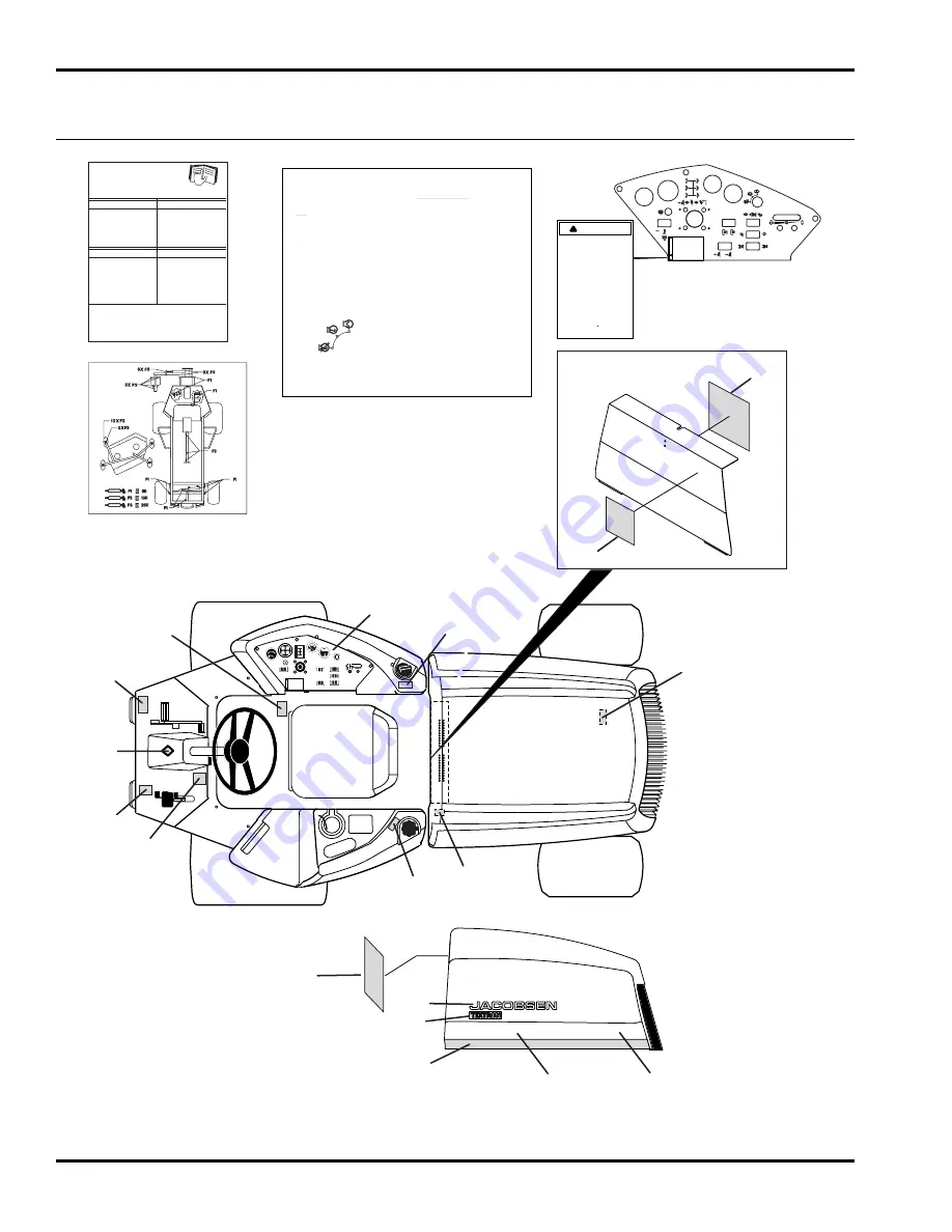
1
2
4
13
12
10
3
7
5
8
6
11
9
15
16
17 / 18
19
14
HR 4600 TURBO
4WD
13
1
. Read oper
ators man
ual bef
ore
oper
ating machine
.
2.
K
eep shields in place and
hardw
are securely
f
astened.
3.
Bef
ore y
ou clean, adjust
or repair this equiptment,
disengage all dr
iv
es
,
engage par
king br
ak
e
and stop engine
.
4.
K
eep hands
, f
eet and
clothing a
w
a
y
from
mo
ving par
ts
.
5.
Ne
v
er carr
y passengers
.
6.
K
eep b
ystanders a
w
a
y.
7.
Do not use on slopes
g
reater than 18 .
!
W
ARNING
1
. Read operators manual before
operating machine.
2. Keep shields in place and
hardware securely
fastened.
3. Before you clean, adjust
or repair this equiptment,
disengage all drives,
engage parking brake
and stop engine.
4. Keep hands, feet and
clothing away from
moving parts.
5. Never carry passengers.
6. Keep bystanders away.
7. Do not use on slopes
greater than 18 .
!
WARNING
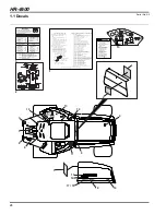
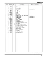
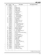
HR-4600
1.1 Decals
Serial No. All

