background image

1    SAFETY

4

1.2

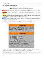
IMPORTANT SAFETY NOTES _______________________________________________

This safety alert symbol is used to alert you to potential hazards.

DANGER

 - Indicates an imminently hazardous situation which, if not avoided, 

WILL

 result in death or serious injury.

WARNING

 - Indicates a potentially hazardous situation which, if not avoided, 

COULD

 result in death or serious 

injury.

CAUTION

 - Indicates a potentially hazardous situation which, if not avoided, 

MAY

 result in minor or moderate injury 

and property damage. It may also be used to alert against unsafe practices.

NOTICE

 - Indicates a potentially hazardous situation which, if not avoided, 

MAY

 result in property damage. It may 

also be used to alert against unsafe practices.

For pictorial clarity, some illustrations in this manual may show shields, guards, or plates, open or removed. Under no 
circumstances should this equipment be operated without these devices securely fastened in place.

By following all instructions in this manual, you will prolong the life of your machine and maintain its maximum 
efficiency. Adjustments and maintenance should always be performed by a qualified technician.

If additional information or service is needed, contact your Authorized Jacobsen Dealer who is kept informed of the 
latest methods to service this equipment and can provide prompt and efficient service. 

Use of other than original or 

authorized Jacobsen parts and accessories will void the warranty.


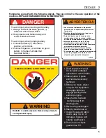
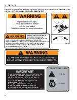
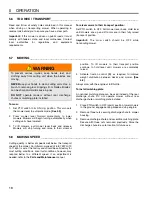
WARNING

The Interlock System on this mower prevents the mower from starting unless 
the brake lever is engaged, PTO switch is off and traction pedal is in neutral. 
The system will stop the engine if the operator leaves the seat without 
engaging the parking brake or setting the PTO switch off.

NEVER operate mower unless the Interlock System is working.

!


WARNING

1.

Before leaving the operator’s position for any reason:

a.

Return traction pedal to NEUTRAL.

b.

Disengage all drives.

c.

Lower all implements to the ground.

d.

Engage parking brake.

e.

Stop engine and remove the ignition key.

2.

Keep hands, feet, and clothing away from moving parts. Wait for all 
movement to stop before you clean, adjust, or service the machine.

3.

Keep the area of operation clear of all bystanders and pets.

4.

Never carry passengers, unless a seat is provided for them.

5.

Never operate mowing equipment without the discharge deflector 
securely fastened in place.

!

Summary of Contents for AR-522 jossa ROPS

Page 1: ...zprovoznit obsluhovat se izovat nebo prov d t jeho servis by si m li p e st celou p ru ku WARNING If incorrectly used this machine can cause severe injury Those who use and maintain this machine shoul...

Page 2: ...3 1 2 Important Safety Notes 4 DECALS INITIAL INSPECTION 3 1 General 9 3 2 Initial Inspection 9 CONTROLS 4 1 Icons 10 4 2 Controls 11 4 3 Control Panel 13 4 4 Operator Alerts 14 OPERATION 5 1 Daily I...

Page 3: ...elds discharge deflectors or other protective devices securely fastened in place 12 Never disconnect or bypass any switch 13 Do not change the engine governor setting or overspeed the engine 14 Carbon...

Page 4: ...tenance should always be performed by a qualified technician If additional information or service is needed contact your Authorized Jacobsen Dealer who is kept informed of the latest methods to servic...

Page 5: ...fijados 3 Antes de limpiar ajustar o reparar este equipo apagar todas los mandos aplicar el freno de estacionamiento y apagar el motor 4 Mantener las manos los pies y la ropa alejados de las piezas e...

Page 6: ...LED USING FASTENERS OF CORRECT SIZE AND GRADE TORQUED TO THEIR SPECIFIED VALUE SEAT BELTS MUST BE WORN WHILE OPERATING VEHICLE 5002952 WARNING TO PREVENT POSSIBLE INJURY TO YOU OR OTHERS DO NOT OPERAT...

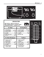
Page 7: ...ss traction pedal 1 Traction Pedal Neutral 2 Mower Switch Off 3 Parking Brake On 4 Throttle Slow 5 Ignition Off 6 Remove Key 1 Follow To Start instructions 2 Throttle Fast 3 Mower Switch Mow 4 Parking...

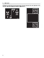
Page 8: ...2 DECALS 8 Familiarize yourself with the following decals They are critical to the safe operation of the machine REPLACE DAMAGED DECALS IMMEDIATELY 3008521 3008522...

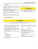
Page 9: ...or scratches Decals provide important operating and safety information Notify dealer and replace all missing or hard to read decals 3 All fluids must be at the full level mark with engine cold Check a...

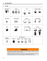
Page 10: ...the icons shown above and what they represent Learn the location and purpose of all the controls and gauges before operating this mower Read Manual High Low Engine Throttle PTO Lock Unlock Forward Re...

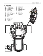
Page 11: ...overs daily If worn or damage replace with original quality parts 8 Do not use on slopes greater than 22 4131828 Total Hours 1 10 0 0 0 0 0 A E M Q U Y B1 B2 F J N S V Z C G K O R W D H L P T X A Tilt...

Page 12: ...adjusting knob on front of seat H Hydraulic Oil Cap Dipstick Fill to mark on dipstick using clean hydraulic fluid while machine is cool Do not overfill J Air Cleaner Indicator Indicates condition of a...

Page 13: ...ystem This system reduces down pressure on decks by pulsing the lift circuit transferring weight to mower Reducing down pressure improves traction but may cause decks to float up creating an uneven cu...

Page 14: ...2 Engine Oil Pressure alarm sounds for 5 seconds then beeps once every three seconds and oil pressure light comes ON Oil pressure low Stop mower immediately lower implements and shut off engine Inspe...

Page 15: ...and repaired if any of the tests fail as listed below the engine does not start in test 1 the engine does start during tests 2 3 or 4 the engine continues to run during tests 5 or 6 3 Refer to the ch...

Page 16: ...10 Disengage the drive motors raise the mowers and slow down when crossing paths or roadways Look out for traffic 11 Stop and inspect the equipment for damage immediately after striking an obstruction...

Page 17: ...throttle to idle and allow engine to operate at no load for three to five minutes 3 Engage parking brake stop the engine and always remove the ignition key If an emergency arises and the mower must b...

Page 18: ...tivate traction control S as required to improve weight distribution between decks and mower See 4 3 Always mow with the engine at full throttle To install mulching plate An optional mulching plate ca...

Page 19: ...after towing Figure 5B 5 10 HILLSIDE OPERATION _____________________________________________________ The mower has been designed for good traction and stability under normal mowing conditions Use caut...

Page 20: ...ne has cooled check coolant level Radiator should be full and recovery bottle should be up to the cold mark 10 Park machine in designated area Engage parking brake and remove key Place key in a secure...

Page 21: ...a cyclical pattern of varying cutting heights resulting in a wave like cut appearance In most cases the wave tip to tip distance is approximately 6 8 in 15 20 cm Color variation light to dark may als...

Page 22: ...ferent from one side of a cutting unit to the other or from one cutting unit to another Check HOC adjustment of cutting units Refer to Parts Maintenance Manual Worn roller bearings or deck caster whee...

Page 23: ...ing in a light green or even brown patch This is usually caused by an excessively low height of cut setting and or uneven turf Probable Cause Remedy HOC height of cut settings are lower than normal Ch...

Page 24: ...of travel Stragglers are scattered blades of uncut or poorly cut grass Probable Cause Remedy Dull cutting blade s Sharpen blade s Refer to Parts Maintenance Manual Mowing ground speed is too fast Red...

Page 25: ...able Cause Remedy Damaged blade s Replace blade s Turning too aggressively Cutting units don t overlap during turns or on side hills Turn less aggressively to allow cutting units to overlap Change mow...

Page 26: ...ippings concentrated at one end of cutting unit s or between cutting units forming line s in the direction of travel Probable Cause Remedy Grass is too tall Mow more often Mowing while grass is wet Mo...

Page 27: ...adjustment from one cutting unit to another Probable Cause Remedy HOC inconsistent from one cutting unit to another Check adjust HOC on cutting units to same height Refer to Parts Maintenance Manual D...

Page 28: ...2 D le it bezpe nostn upozorn n 4 2 T TKY 3 PRVN PROHL DKA 3 1 V eobecn informace 9 3 2 Prvn prohl dka 9 4 OVL DAC PRVKY 4 1 Ikony 10 4 2 Ovl dac prvky 11 4 3 Ovl dac panel 13 4 4 Varov n pro obsluhu...

Page 29: ...mi za zen mi bezpe n p ipevn n mi na sv m m st 12 Nikdy neodpojujte ani nep emost ujte dn vyp na e 13 Nikdy nem te nastaven omezova e motoru a motor nep et ejte 14 Oxid uhelnat obsa en ve v fukov ch...

Page 30: ...konnost Se izov n a dr bu mus v dy prov d t kvalifikovan technik V p pad pot eby dodate n ch informac kontaktujte autorizovan ho prodejce spole nosti Jacobsen kter je informov n o nejnov j ch postupe...

Page 31: ...35 DR TE RUCE A NOHY MIMO POHYBUJ C SE SOU STI NEBEZPE 8 3 5 8 9 2 VAROV N Chladi je pod tlakem Odstra ujte v ko pomalu aby nedo lo ke zran n 365956 VAROV N 1 P e t te si n vod k obsluze Nedovolte nev...

Page 32: ...AN S POU IT M UPEV OVAC CH PRVK SPR VN VELIKOSTI A JAKOSTI UTA EN CH S P EDEPSAN M MOMENTEM B HEM PROVOZU VOZIDLA JE NUTN POU VAT BEZPE NOSTN P SY VAROV N NEPRACUJTE SE STROJEM BEZ NASAZEN CH OCHRANN...

Page 33: ...l pn te ped l pojezdu 1 Ped l pojezdu Neutr l 2 Sp na seka ky Vypnut 3 Ru n brzda Zata en 4 Plyn Pomalu 5 Zapalov n Vypnut 6 Vyt hn te kl 1 Postupujte podle pokyn pro spu t n 2 Plyn Rychle 3 Sp na sek...

Page 34: ...2 T TKY 8 D kladn se seznamte se t tky Jsou nezbytn nutn pro bezpe n provoz stroje PO KOZEN T TKY OKAM IT VYM TE 3008521 3008522...

Page 35: ...dejce a vym te v echny chyb j c nebo patn iteln t tky 3 P i vychladl m motoru mus kapaliny dosahovat na zna ku maxim ln hladiny Kontrola a Hladina chladic kapaliny v chladi i b Hladina motorov ho olej...

Page 36: ...stavuj P ed zapo et m pr ce s traktorem si zapamatujte um st n a el v ech ovl dac ch prvk a ukazatel P e t te si Vysok N zk Plyn motoru Pomocn pohon Blokov n Odblokov n Dop edu Zp te ka Pojezd Tempoma...

Page 37: ...e with original quality parts 8 Do not use on slopes greater than 22 4131828 Total Hours 1 10 0 0 0 0 0 A E M Q U Y B1 B2 F J N S V Z C G K O R W D H L P T X A P ka skl p n sloupku zen B1 Zam en ru n...

Page 38: ...ny pod sedadlem ot ejte nastavovac m knofl kem na p edn stran sedadla H V ko m rka n dr e hydraulick ho oleje Napl te po rysku na m rce istou hydraulickou kapalinou kdy je stroj studen Nep epl ujte J...

Page 39: ...trakce Stisknut sp na e aktivuje syst m kontroly trakce v dic jednotce Tento syst m sni uje tlak na seka ky pulsacemi zvedac ho okruhu kter p en v hu na seka ku Sn en tlaku zlep uje trakci ale m e zp...

Page 40: ...o dobu 5 sekund a pak se spou t p eru ovan ka d t i sekundy rozsv t se kontrolka tlaku oleje Tlak oleje je n zk Okam it zastavte traktor spust te p pojn za zen dol a vypn te motor Zkontrolujte hladinu...

Page 41: ...kter z n e uveden ch kontrol neprob hne sp n l motor nelze p i testu 1 nastartovat l motor se b hem test 2 3 nebo 4 nastartuje l motor se nezastav b hem test 5 nebo 6 3 Postupujte podle n sleduj c ch...

Page 42: ...ejte pozor na provoz na silnici 11 Pokud stroj za ne nestandardn vibrovat nebo pokud naraz te do n jak p ek ky okam it zastavte a za zen prohl dn te zda nen po kozeno P ed pokra ov n m v pr ci nechte...

Page 43: ...ust te p pojn za zen na zem zat hn te ru n brzdu sni te ot ky na volnob h a nechte motor t i a p t minut b et bez zat en 3 Zat hn te ru n brzdu vypn te motor a v dy vyt hn te kl ze sp nac sk ky Pokud...

Page 44: ...lohy p idr te p ku a se seka ky pln zvednou 4 Podle pot eby aktivujte kontrolu trakce S abyste zlep ili rozlo en hmotnosti seka ky Viz 4 3 V dy sekejte s motorem na pln plyn Mont mul ovac desky M sto...

Page 45: ...til a po odta en vrat te kryt na m sto Obr 5B 5 10 PR CE VE SVAHU _________________________________________________________ Seka ka byla zkonstruov na pro dobrou trakci a stabilitu za norm ln ch provo...

Page 46: ...olujte hladinu chladic kapaliny Chladi mus b t pln a vyrovn vac n dr ka mus b t pln a ke zna ce studen kapaliny 10 Zaparkujte stroj v ur en m prostoru Zat hn te ru n brzdu a vyndejte kl ek Ulo te kl e...

Page 47: ...r vede k vlnit mu vzhledu posekan ho tr vn ku Ve v t in p pad je kol s n vlny p ibli n 15 20 cm Je tak mo n zaznamenat kol s n barvy sv tl a tmav Tento stav je obvykle zp soben k vav m pohybem sekac c...

Page 48: ...kac jednotky nebo na jedn sekac jednotce jin ne na druh Zkontrolujte nastaven v ky sek n sekac ch jednotek Viz katalog d l a n vod k dr b Opot ebovan lo iska v lc nebo kole ka Zkontrolujte resp vym te...

Page 49: ...elen m nebo dokonce hn d m pol m Je to obvykle zp sobeno nadm rn mal m nastaven m v ky sek n resp nerovnostmi tr vn ku Mo n p ina N prava Nastaven v ky sek n je ni ne norm ln Zkontrolujte a upravte na...

Page 50: ...uje sm r pojezdu Nepravidelnosti jsou rozpt len pole neposekan nebo patn posekan tr vy Mo n p ina N prava Tup sekac lopatky Naost ete lopatky Viz katalog d l a n vod k dr b Rychlost sek n je p li vyso...

Page 51: ...o n p ina N prava Po kozen lopatky Vym te lopatky Ot en p li agresivn B hem ot en nebo na bo n ch svaz ch se sekac jednotky nep ekr vaj Ot ejte se m n agresivn aby se sekac jednotky mohly p ekr vat M...

Page 52: ...h na jednom konci sekac ch jednotek nebo mezi dv ma sekac mi jednotkami s n sledn m vytv en m dku ve sm ru pojezdu Mo n p ina N prava Tr va je p li vysok Sekejte ast ji Sek n kdy je tr va vlhk Sekejte...

Page 53: ...jednotkami Mo n p ina N prava Nekonzistentn v ka sek n mezi jednotliv mi sekac mi jednotkami Zkontrolujte resp upravte v ku sek n sekac ch jednotek na stejnou rove Viz katalog d l a n vod k dr b Rozd...

Page 54: ......

Page 55: ......

Page 56: ...ISO 14001 registration at all our manufacturing locations A worldwide dealer network and factory trained technicians backed by Jacobsen Parts Xpress provide reliable high quality product support Vyba...

Reviews: