3 ADJUSTMENTS
10
3.6
FORWARD / REVERSE SPEED ______________________________________________
Forward and reverse speeds are adjusted at the traction
pedal. Set forward speed before adjusting reverse.
To adjust forward speed:
1.
Make sure drive pump has been set to Neutral and
engine throttle is adjusted correctly.
2.
Start engine and check forward travel speed with
engine at full throttle and mower in two wheel drive
(2WD). Forward transport speed should measure 10
mph (16 kph).
3.
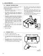
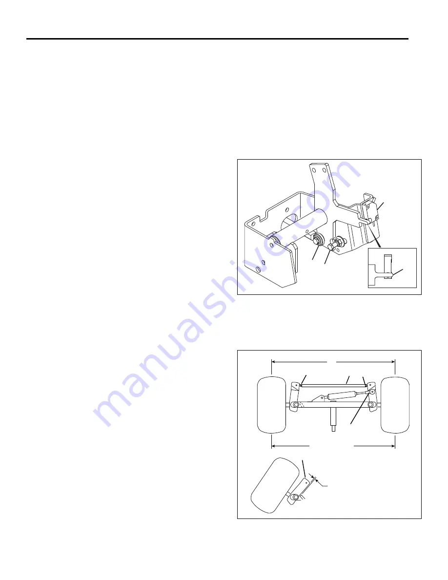
Stop engine. To adjust forward speed, disconnect eye
bolt
(K)
from pedal and loosen jam nut. Turn eye bolt
in to reduce speed, out to increase speed. Tighten jam
nut to hold adjustment in place and connect eye bolt.
4.
With traction pedal in Neutral, check position of Neutral
switch
(J)
. Adjust switch up or down so pointer
(M)
on
traction pedal bracket is centered over it. When
adjusted correctly lamp 5 on controller will light when
ignition switch is turned to on.
5.
Start engine and check forward speed. Repeat
procedure until 10 mph (16 kph) forward transport
speed is attained.
To adjust reverse speed:
1.
Set forward speed.
2.
Start engine and check reverse travel speed with
engine at full throttle. Reverse speed should measure
3.5 mph (5.6 kph).
3.
Stop engine. To adjust reverse speed, loosen nut on
reverse travel stop bolt
(L)
. Slide bolt forward in slotted
hole to increase speed, back to reduce speed. Tighten
nut to hold adjustment in place.
4.
Start engine and check speed. Repeat procedure until
3.5 mph (5.6 kph) reverse speed is attained.
Figure 3E
3.7
STEERING TOE-IN _________________________________________________________
1.
Turn wheels to straight ahead position.
2.
Loosen jam nuts
(N)
on both sides of tie rod
(M)
.
3.
Turn tie rod
(S)
to provide proper toe-in. Toe-in must
not 1/16 in. (+1.5 mm)
(P)
. Retighten jam
nuts.
4.
After adjusting tie rod, adjust steering cylinder by
threading the rod
(T)
in or out of ball joint so spindle
arm
(R)
clears the stop on the axle by 3/4 ± 1/16 in.
(19 ± 1.5 mm)
(U)
when cylinder is fully extended.
Figure 3F
J
K
L
M
3/4 ± 1/16 in.
(19 ± 1.5
mm)
N
S
T
U
P
P
+0 to1/16”
R
(+0 to 1.5 mm)
LF016
N


