background image

4    CONTROLS

20

Display

Description

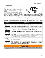
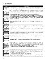
To enter Maintenance Mode, press either orange buttons 

(K or L)

 until Maintenance Mode PIN

screen is on the display and press black button 

(J)

. Use the orange buttons 

(K or L) 

to select and

the black button 

(J) 

to enter the digits for the Mechanic Mode pin.

NOTE:

 The default PIN for Maintenance Mode is 

6789

.  


The Maintenance Mode PIN can be

customized to a setting of your choice. Please contact your Jacobsen Dealer or Jacobsen
Technical Support (1800-848-1636 Option 2) for complete instructions.

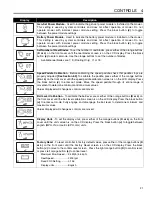
Maintenance Hours

 - System can track up to 999.9 hours for maintenance purposes.

To reset maintenance hours, press either of the orange buttons 

(K or L) 

on the front cover until

the maintenance hours screen is on the LCD display. Press the black button 

(J)

 to move to the

confirm reset screen. Press the right orange button 

(K)

 to confirm reset, or press left orange

button 

(L)

 to cancel reset.

Backlap Select

 - Used to switch mower to backlap mode. See 

Section 11.4

 for backlap screen

descriptions.

Set FOC

 - To set the fixed FOC, press either of the orange buttons 

(K or L) 

on the front cover

until the FOC set screen is on the LCD display. Press the black button 

(J) 

to enter set mode. Use

the orange buttons to raise 

(K) 

or lower 

(L) 

the FOC value to the desired setting. press the black

button to set speed.

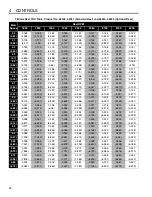
Fixed FOC setting must be 0 or between 0.087 and 0.178 in. (2.2 and 4.5 mm). 

[See Section

4.4].

Traction Motor Current

 - Displays current draw of traction drum motor. Fault will be displayed if

current draw is greater than 30 Amps for one second.

Reel Motor Current

 - Displays current draw of reel motor. Fault will be displayed if current draw

is greater than 30 Amps for one second.

Total Motor Current

 - Displays total current draw of traction drum motor and reel motor.

Maximum Mow Speed

 -


To set the maximum mow speed, press either of the orange buttons 

(K

or L) 

on the front cover until the set max mow speed screen is on the LCD display. Press the

black button 

(J) 

to enter set mode. Use the orange buttons to raise 

(K) 

or lower 

(L) 

the maximum

mow speed to the desired speed. press the black button to set speed.

Maximum mow speed must be between 2.0 and 3.8 MPH (3.2 and 6.1 kph).

Fixed Reel Speed: 

To set the fixed reel speed, the FOC setting must be set to 0, then press

either of the orange buttons 

(K or L) 

on the front cover until the set reel speed screen is on the

LCD display. Press the black button 

(J)

 to enter set mode. Use the orange buttons to raise 

(K) 

or

lower 

(L) 

the reel speed to the desired setting.

Fixed reel speed must be set between 1800 and 2200 rpm.

The Maximum Mow Speed and the Fixed Reel Speed are used to determine the FOC
(Frequency of Cut) 

[See Section 4.4].

Summary of Contents for Eclipse 2

Page 1: ...F Floating 18 11 Blade Reel Gen Set 63345 Eclipse 2 118F Floating 18 11 Blade Reel Battery Pack 63337 Eclipse 2 118F Floating 18 15 Blade Reel Gen Set 63346 Eclipse 2 118F Floating 18 15 Blade Reel Ba...

Page 2: ...r emits chemicals known to State of California to cause cancer and birth defects or other reproductive harm FOREWORD Suggested Stocking Guide To Keep your Equipment fully operational and productive Ja...

Page 3: ...Belts 35 6 6 Front Roller Weight 36 6 7 Torque Specification 37 7 FIXED HEAD REEL ADJUSTMENTS 7 1 General 38 7 2 Reel To Bedknife 38 7 3 Bedknife Adjustment 39 7 4 Cutting Height 39 8 FLOATING HEAD R...

Page 4: ...cted to themselves to bystanders and damage to property 11 Never operate equipment that is not in perfect working order or is without decals guards shields discharge deflectors or other protective dev...

Page 5: ...uctions in this manual you will prolong the life of your machine and maintain its maximum efficiency Adjustments and maintenance should always be performed by a qualified technician If additional info...

Page 6: ...63339 Eclipse 122 base unit with 22 in 559 mm 15 blade reel and InCommand control system Gen Set power module 63348 Eclipse 122 base unit with 22 in 559 mm 15 blade reel and InCommand control system B...

Page 7: ...____________ Gen Set Mowers Weights Without Grass Catcher Lbs kg 63334 Eclipse 118 11 Blade 214 97 1 63335 Eclipse 118 15 Blade 217 98 4 63336 Eclipse 118F 11 Blade 254 115 2 63337 Eclipse 118F 15 Bla...

Page 8: ...Phone Number 800 777 1096 Fax Number 336 723 1098 E Mail billedi bellsouth net E Mail Contact Name Bill Turner URS Electronics 123 N E 7th Portland OR 97232 Phone Number 800 955 4877 Fax Number 503 2...

Page 9: ...d Head Turf Groomer Adapter Kit 67965 MAGKnife Kits 122F Super Tournament MAGKnife Kit 4188500 122F Tournament MAGKnife Kit 4158083 122 Super Tournament MAGKnife Kit 4158082 Does not included batterie...

Page 10: ...vadinimas Isem tal Magna Nazwa urz dzenia Nome da M quina Numele echipamentului N zov stroja Naziv stroja Nombre de la m quina Maskinens namn Eclipse 118 Hybrid 11 Blade Eclipse 118 Hybrid 15 Blade Ec...

Page 11: ...14 E m istes Direktiivin 2000 14 EY mukainen ilmoitettu tarkastuslaitos Isossa Britanniassa Organisme notifi concernant la directive 2000 14 CE Britische benannte Stelle f r 2000 14 EG 2000 14 2000 1...

Page 12: ...nisko re istru un kura ir apstiprin ta Kopien Asmuo kuris yra gana inomas kuriam gamintojas suteik galiojimus sudaryti i deklaracij ir kuris j pasira turi vis technin informacij ir yra galiotas sudary...

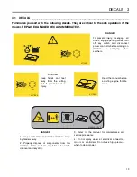
Page 13: ...ct power connector before working on machine or emptying grass catchers DANGER Keep hands and feet away from the cutting unit to prevent serious injury DANGER 1 Keep a safe distance from the machine K...

Page 14: ...critical to the safe operation of the mower REPLACE DAMAGED DECALS IMMEDIATELY 4265170 4265171 4172240 Read the manual before adjusting front roller weight Disengaged Parking Engaged Brake Reel Switc...

Page 15: ...DECALS 3 15 To Engage Traction 1 Slide bail to the left 2 Squeeze bail to handle...

Page 16: ...positions OFF RUN and START Key switch must be in RUN position to start units equipped with Gen Set power module E Reel Switch The reel switch is used to start and stop the reel F LCD Controls Used t...

Page 17: ...ered mowers for 30 seconds and a solid tone alarm will sound Press the black button J to silence the alarm Return mower to storage area or install a fully charged battery pack Reel motor will not oper...

Page 18: ...or rises above 60 volts FOC Setting Displays FOC Frequency of Clip setting When FOC is set to 0 reel will operate at the fixed reel speed Fixed Reel Speed Displays fixed reel speed setting with FOC s...

Page 19: ...ge travel speed set FOC reel speed traction motor current draw reel motor current draw total motor current draw set mow speed set reel speed set power source set number of reel blades calibrate speed...

Page 20: ...L the FOC value to the desired setting press the black button to set speed Fixed FOC setting must be 0 or between 0 087 and 0 178 in 2 2 and 4 5 mm See Section 4 4 Traction Motor Current Displays cur...

Page 21: ...K or L on the front cover until the speed paddle calibration screen is on the LCD display Press the black button J to enter set mode Move the speed paddle through its entire range of movement to deter...

Page 22: ...ting Changing the FOC setting to a value other than 0 will enable the fixed FOC mode and disable the reel speed setting As mower travel speed increases or decreases reel speed will automatically adjus...

Page 23: ...246 2 195 2 80 0 110 0 107 0 104 0 101 0 099 0 096 0 094 0 092 0 090 4 51 2 782 2 706 2 635 2 568 2 503 2 442 2 384 2 329 2 276 2 90 0 113 0 110 0 107 0 105 0 102 0 100 0 097 0 095 0 093 4 67 2 881 2...

Page 24: ...118 2 993 2 8 4 51 0 149 3 793 0 145 3 691 0 141 3 593 0 138 3 501 0 134 3 414 0 131 3 33 0 128 3 251 0 125 3 176 0 122 3 103 2 9 4 67 0 155 3 929 0 150 3 822 0 147 3 722 0 143 3 626 0 139 3 536 0 136...

Page 25: ...178 0 173 0 168 0 164 0 160 0 156 0 153 0 149 4 51 4 636 4 511 4 392 4 279 4 172 4 071 3 974 3 881 3 793 2 9 0 189 0 184 0 179 0 174 0 170 0 166 0 162 0 158 0 155 4 67 4 802 4 672 4 549 4 432 4 321 4...

Page 26: ...703 2 8 0 235 0 228 0 222 0 217 0 211 0 206 0 201 0 196 0 192 4 51 5 961 5 799 5 647 5 502 5 364 5 234 5 109 4 99 4 877 2 9 0 243 0 236 0 230 0 224 0 219 0 213 0 208 0 203 0 199 4 67 6 173 6 007 5 848...

Page 27: ...arting and for restarting a warm engine P Fuel Valve Lever The fuel valve opens and closes the connection between the fuel tank and the carburetor The fuel valve lever must be in the ON position for t...

Page 28: ...m as soon as the operator releases the O P C Operator Presence Control bail 2 To test the system a Place mower on the kickstand b Make certain reel switch is off 3 Gen Set Power Module Start the engin...

Page 29: ...rs and or damage the equipment 9 Disengage the reel switch to stop blades when not mowing 10 Disengage the reel switch when crossing paths or roadways Look out for traffic 11 Stop and inspect the equi...

Page 30: ...elease LCD display G should show startup display for 5 seconds then switch to system voltage If system fails to initialize check to see if power connector is properly attached 4 Check system voltage o...

Page 31: ...r right hand This method makes it possible to turn around quickly with very few steps Figure 5C 4 To assure complete even cutting overlap swaths by 1 to 2 in 25 to 50 mm then make one or more passes a...

Page 32: ...disconnect power connector Figure 5E 5 7 KICKSTAND ______________________________________________________________ 1 To put the mower on the kickstand a Use your foot to rotate kickstand down to the gr...

Page 33: ...l with care it is highly flammable Use an approved container The spout must fit inside the fuel filler neck Avoid using cans and funnels to transfer fuel 6 Store fuel according to local state or feder...

Page 34: ...the brake cable then tighten nut A 2 If adjustments cannot be made at the handle remove the transport wheel and make the adjustment at the brake band 3 Loosen screw C and pull cable to obtain desired...

Page 35: ...16 18 x 1 hex head screw K and 5 16 18 hex nut L to bottom of bearing bracket H Loosen nuts J 2 Place bedknife gauge bar M on top of roller and under screw K Tighten screw K until belt G deflects 1 1...

Page 36: ...roller weight slide battery tray U or engine W towards rear of mower c Use the decal on the power module mount as a guide for adjusting the front roller weight Aligning the oil drain Gen Set or the V...

Page 37: ...n lb Nm 75 8 4 100 11 3 107 12 1 143 16 1 9 16 18 ft lb Nm 92 124 122 165 129 174 172 233 1 4 28 in lb Nm 85 9 6 115 13 0 120 13 5 163 18 4 5 8 11 ft lb Nm 113 153 151 204 159 215 211 286 5 16 18 in l...

Page 38: ...e front face of the bedknife Use a standard flat file to dress the bedknife 3 If wear or damage is beyond the point where the reel or bedknife can be corrected by the lapping process they must be regr...

Page 39: ...eel when the paper is held at 90 to the bedknife Figure 7B Figure 7C 7 4 CUTTING HEIGHT _________________________________________________________ Note Make sure the bedknife is properly adjusted befor...

Page 40: ...ess the bedknife 3 If wear or damage is beyond the point where the reel or bedknife can be corrected by the lapping process they must be reground 4 Proper reel to bedknife adjustment is critical A gap...

Page 41: ...in freely and you should be able to cut a piece of newspaper along the full length of the reel when the paper is held at 90 to the bedknife 4 Return mower to upright position Limit bracket A is spring...

Page 42: ...6 REEL ASSEMBLY REMOVAL ________________________________________________ The reel assembly can be removed for maintenance or to use a different reel 1 Remove hairpin and washer and slide the lift han...

Page 43: ...he body and eyes with extended flushing with clear water Contact a physician immediately Always wear a safety shield or approved safety goggles when charging batteries Hydrogen is explosive in concent...

Page 44: ...will be left on the batteries which is conductive and will contribute to the discharge of the batteries The correct cleaning technique is to spray the top and sides of the batteries with a solution o...

Page 45: ...e battery charger is used with 115 V 60 Hz North America input voltage only If you live in an area where 115 V 60 Hz input voltage is not used a new AC power cord must be purchased locally The battery...

Page 46: ...wn in Figure 9C and tighten the battery post hardware securely Protect the battery terminals and battery wire terminals with a commercially available protective coating Battery Pack Assembly 1 Install...

Page 47: ...e battery pack 1 Park mower on a solid level area 2 Set parking brake and remove key from switch 3 Disconnect battery connector B place mower on kickstand 4 Push and hold battery release latch C down...

Page 48: ...operating temperature before operating at full load 3 Change the engine oil after the first 20 hours of operation 4 Refer to Section 13 2 and Engine Manual for specific maintenance intervals 10 2 ENG...

Page 49: ...r 30 seconds Shut engine off Wait 30 seconds and check oil level Add oil to bring up to FULL level Use only SAE 10W30 engine oils with API classification SG SF CC CD Figure 10B 10 4 ENGINE SPEED _____...

Page 50: ...to become empty Use clean fresh regular grade unleaded gasoline minimum 86 Octane See engine manual before using oxygenated blended fuel Do not fill above the fuel filler neck WARNING Never remove th...

Page 51: ...otor check to be sure motor connections are tight 11 2 TIRES OPTION ___________________________________________________________ 1 Keep tires properly inflated to prolong tire life Check pressure only...

Page 52: ...minute timer to end selecting Cancel placing reel switch E in the OFF position moving the O P C bail C moving the thumb lever B or turning key switch D to the OFF position 6 Turn key switch D to off p...

Page 53: ...scharge the battery Disconnect the charging plug from the mower power connector The batteries must be cleaned and all deposits neutralized and removed from the battery case to slow self discharge The...

Page 54: ...l 3 Fuel Shut off valve closed 3 Open fuel shut off valve 4 Engine Spark Plug 4 See Engine Manual 5 Engine switch off 5 Turn engine switch to On Engine hard to start or runs poorly looses power or sta...

Page 55: ...te point L4 remove L H transport wheel and mounting bracket E to gain access to fitting Turn the traction drum if pulley F is blocking the fitting then insert grease gun through hole and carefully app...

Page 56: ...___ F C D B A L 4 L 6 L 6 L7 E L 3 L L5 2 L1 L L5 L5 2 L 2 L1 L1 L1 L1 L1 L1 Reel Roller Bearing L2 Reel Motor Bearing Housing L3 Right Side Traction Drum Bearing Housing L4 Left Side Traction Drum Be...

Page 57: ...ts list 5 Send or bring the order to an authorized Jacobsen Distributor 6 Inspect all shipments on receipt If any parts are dam aged or missing file a claim with the carrier before accepting 7 Do not...

Page 58: ...58 DRY ERASE MARKER ONLY 1 2 3 4 5 6 6 29 7 8 9 9 10 11 12 13 14 15 16 17 18 19 20 21 21 22 22 23 23 24 24 25 25 26 27 28 4265172 4265171 4265170 ECLIPSE2 1 1 Handle Covers Serial No All...

Page 59: ...258830 1 Cable 38 1 2 Brake Eclipse2 126 Left Side 13 4258830 1 Cable 38 1 2 Brake Eclipse2 118 118F Right Side 13 4258790 1 Cable 40 1 2 Brake Eclipse2 122 122F 126 Right Side 14 4253551 1 Controller...

Page 60: ...60 1 2 3 4 5 6 6 7 8 9 10 11 12 13 14 26 15 16 17 18 19 20 21 22 23 24 25 ECLIPSE2 2 1 Handle Assembly Serial No All...

Page 61: ...1 Spring Washer 7 16 11 4137303 1 Plate Throttle 12 422504 1 Set Screw 10 32 x 3 8 13 4128933 4 Screw 5 16 18 x 1 1 2 Hex Socket 14 444718 4 Locknut 5 16 18 Hex Center 15 4256692 1 Cable OPC 16 43403...

Page 62: ...4 5 6 7 8 8 9 10 10 11 11 12 12 13 Eclipse2 118 and 118F 63334 63343 63335 63344 63336 63345 63337 63346 Eclipse2 122 122F and 126 63338 63347 63339 63348 63340 63349 63341 63350 63342 63351 Handle A...

Page 63: ...e Eclipse2 122 122F 126 Right Side 7 2809901 1 Torsion Spring Handle Eclipse2 118 118F Right Side 7 2809901 1 Torsion Spring Handle Eclipse2 122 122F 126 Left Side 8 455012 2 Flat Washer 1 2 9 456006...

Page 64: ...19 20 15 16 16 16 16 17 36 12 4172240 14 18 A B A B A B A B A B 21 Gen Set Battery 22 23 23 24 24 24 24 25 25 26 26 27 28 28 29 30 31 31 32 33 33 34 35 ECLIPSE2 4 1 Power Module Mounting Plate Serial...

Page 65: ...en Set Power Module Only 15 4259130 1 Bracket Controller Cover 16 453009 4 Flat Washer 5 16 17 4257467 1 Plate Power Module Mounting 18 4255551 4 Stud Iso Mount Gen Set Power Module Only 19 4265710 1...

Page 66: ...CHARLOTTE NC YEAR OF PRODUCTION MADE IN U S A A Textron Company 1 1 2 2 3 3 3 3 4 4 4 4 4 4 4 4 5 5 5 5 5 5 5 5 6 6 6 6 7 7 7 7 8 8 8 8 9 9 9 9 10 10 10 10 11 11 11 11 12 13 14 15 If 2 Bolt Spindle Mo...

Page 67: ...69640 1 Decal Danger 9 REF 1 Serial Plate 10 800710 2 Screw 5 16 18 x 1 Hex Flange Eclipse2 122 122F and 126 11 4258190 2 Bracket Handle Mount Eclipse2 122 122F and 126 12 400192 1 Screw 5 16 18 x 1 1...

Page 68: ...18 19 20 21 22 23 24 25 26 27 28 28 29 30 31 ECLIPSE2 6 1 Lower Unit Fixed Head Units Serial No 63334 All Serial No 63335 All Serial No 63338 All Serial No 63339 All Serial No 63342 All Serial No 6334...

Page 69: ...4104720 3 O Ring 14 434036 3 Screw 5 16 18 x 1 1 4 Hex Socket 15 446136 6 Lockwasher 5 16 Heavy 16 471214 1 Grease Fitting 1 4 20 Straight 17 367029 1 Nut 3 4 16 Nylock Hex Jam Nut 18 367164 1 Spacer...

Page 70: ...2 High Profile 4234900 22 Championship 5002887 22 Super Tournament Standard Bedknife 5000141 26 Heavy Section Reels Part Number Description 4170202 18 11 Blade Reel 4225502 18 15 Blade Reel 4172945 22...

Page 71: ...Bearing Cup and Cone 10 4128725 1 Grease Fitting 11 458013 1 Snap Ring 12 5002151 1 Spring 13 304745 1 Washer 14 364900 1 Nut 3 4 16 Reel 15 365501 2 Screw Bedknife Backing 16 454017 2 Spring Washer 7...

Page 72: ...19 18 18 8 10 4127335 ECLIPSE2 8 1 Grass Shield and Roller Brackets Fixed Head Units Only Serial No 63334 All Serial No 63335 All Serial No 63338 All Serial No 63339 All Serial No 63342 All Serial No...

Page 73: ...nting R H 4 241927 1 Bracket Catcher Mounting L H 5 2000072 2 Bracket Roller Adjusting 6 343616 2 Stud Front Roller Adjusting 7 3005692 2 Adjusting Knob 8 441677 4 Carriage Bolt 5 16 18 x 1 1 2 9 4447...

Page 74: ...27 29 29 30 30 30 30 31 32 36 37 37 38 35 33 34 34 29 29 30 30 28 28 25 40 ECLIPSE2 9 1 Floating Head Reel Connection Floating Head Units Only Serial No 63336 All Serial No 63337 All Serial No 63340 A...

Page 75: ...3 4140151 1 Mount Right Side Catcher 14 471221 1 Grease Fitting 1 4 28 90 15 460312 4 Hairpin 16 366317 1 Rod End 3 8 24 17 4104720 1 O Ring Motor 18 4261470 1 Motor Brushless Bi Directional Reference...

Page 76: ...3 1 2 6 6 21 22 23 24 25 26 28 28 28 4127335 ECLIPSE2 10 1 Outer Reel Assembly Floating Head Units Only Serial No 63336 All Serial No 63337 All Serial No 63340 All Serial No 63341 All Serial No 63345...

Page 77: ...d 63346 10 4174640 1 Shield Reel 22 Used on 63340 63349 63341 and 63350 11 403782 2 Screw 1 4 20 x 3 4 Truss Head 12 443102 4 Nut 1 4 20 Hex 13 453023 2 Flat Washer 1 4 14 343616 2 Stud 15 352737 2 Sc...

Page 78: ...per Tournament Standard Style Bedknives Secured with screws Part Number Description 5000098 18 Low Profile 5002888 18 Super Tournament 4234901 18 Championship 503478 22 Low Profile 503477 22 High Prof...

Page 79: ...Blade 22 Left Hand Reel Optioanl Reel 5 1004756 1 Bearing Housing 6 500534 1 Bearing Cup and Cone 7 336962 1 Seal Grease 8 471214 1 Grease Fitting 9 471242 1 Vent Fitting 10 445795 8 Nut 5 16 18 Spira...

Page 80: ...80 24 22 21 23 26 27 29 19 17 31 25 25 28 30 2 5 4 6 7 8 1 12 12 13 13 14 10 16 14 3 1 15 15 11 9 18 28 20 19 24 32 ECLIPSE2 12 1 Differential and Rollers Serial No All...

Page 81: ...835 1 Differential 11 463017 1 Key 9 Woodruff 12 308030 2 Thrust Washer 13 202947 2 Pinion Gear 14 415563 2 Set Screw 7 16 20 x 3 8 15 463007 2 Key 7 Wooodruff 16 308028 1 Pinion Shaft 17 220318 1 Bea...

Page 82: ...82 7 8 1 24 16 16 13 17 25 33 6 4 2 9 5 3 3 18 17 35 35 36 34 28 29 19 32 14 14 22 23 16 16 13 21 20 12 11 12 10 15 15 31 27 30 26 4 ECLIPSE2 13 1 Parking Brake and Wheels Serial No All...

Page 83: ...Collar 16 366697 4 Bushing 17 446136 4 Lockwasher 5 16 Heavy 18 400188 2 Screw 5 16 18 x 1 Hex Head 19 361451 1 Washer Left Side Only 20 415513 2 Set Screw 1 4 20 x 1 2 21 366742 2 Brake Band Pin 22...

Page 84: ...18 27 31 15 17 17 17 19 19 19 20 20 20 11 13 16 16 21 1 2 3 4 5 6 7 9 14 14 17 22 23 24 25 26 28 29 30 32 32 33 33 10 ECLIPSE2 14 1 Belts and Drive Motors Serial No All Fixed Head Frame Shown Floating...

Page 85: ...367554 2 Bearing Needle 15 446130 2 Lockwasher 1 4 Heavy 16 444708 3 Locknut 1 4 20 Center 17 400190 4 Screw 5 16 18 x 1 1 4 Hex Head 18 452006 3 Flat Washer 5 16 19 446136 3 Lockwasher 5 16 Heavy 20...

Page 86: ...ontroller Connection J6 and J7 Reel Motor Controller Connection J10 and J11 Reel Motor Connection J12 and 13 Traction Motor Connection M1 Reel Motor M2 Traction Motor GC1 GC2 J22 and J24 Engine Shutdo...

Page 87: ...Motor REFERENCE U1 See 19 1 4 1 3 4261770 1 Motor Brushless Bi Directional REFERENCE M1 See 19 1 6 1 9 1 4 4253190 1 Controller Traction Motor REFERENCE U2 See 19 1 4 1 5 4261770 1 Motor Brushless Bi...

Page 88: ...6 17 17 18 19 20 20 21 ECLIPSE2 16 1 Genset Power Source 63305 Serial No 63334 All Serial No 63335 All Serial No 63336 All Serial No 63337 All Serial No 63337 All Serial No 63338 All Serial No 63339 A...

Page 89: ...8 x 1 1 2 8 452010 4 Flat Washer 3 8 9 548911 4 Nut 5 16 18 Hex Flange 4258510 1 Generator Eclipse II REFERENCE U3 See 19 1 10 N S 1 Generator Adapter Base 11 N S 1 O Ring 2 O D 12 N S 1 O Ring 2 1 4...

Page 90: ...10 11 12 13 14 ECLIPSE2 17 1 Battery Power Source 63306 Serial No 63343 All Serial No 63344 All Serial No 63345 All Serial No 63346 All Serial No 63347 All Serial No 63348 All Serial No 63349 All Seri...

Page 91: ...2 8 Nut 1 4 20 Hex 4 446130 4 Lockwasher 1 4 Heavy 5 441604 4 Carriage Bolt 1 4 20 x 1 6 400108 2 Screw 1 4 20 x 3 4 Hex Head 7 443106 3 Nut 5 16 18 Hex 8 446136 3 Lockwasher 5 16 Heavy 9 452006 3 Fla...

Page 92: ...8 10 10 To Battery Gauge 10 10 10 10 12 22 11 23 21 13 14 15 26 27 24 6 6 18 19 20 20 16 17 25 P N KEY Battery and Battery Monitor Connections 7 9 9 9 9 14 See Above 7 4170001 STOP 2 5 4 1 6 6 3 A A E...

Page 93: ...x 5 8 Hex Head 11 444306 8 Nut 8 32 Hex 12 446112 8 Lockwasher 8 Heavy 13 4101600 2 Strap Battery Case 14 4245270 1 Gauge Battery Reference U4 See 19 1 15 2811221 1 Lid Battery Case Includes Decals 16...

Page 94: ...ed Red Yel Reel Motor Speed Reel Motor Dir Reel Motor Enable Reel Motor Gnd Grn J2 21 Blu J2 9 Wht J2 8 Blk J2 10 Reel Motor Temp Red J2 12 Reel Motor Tach Brn J2 17 CAN High CAN Low CAN Shield Red J2...

Page 95: ...B Shield J10 4 Blk Wht Red Gn Ye Org Yel Grn Gy Brn Blu Gn Ye Blk Wht Red Gn Ye Shield Motor Case J12 4 HALL B HALL C Signal Gnd Temp J13 3 J13 4 J13 5 J13 6 HALL A J13 2 5V Output Motor Speed Motor D...

Page 96: ...21 48V Work Light Part of optional light kit 63320 M1 See 6 1 or 9 1 4261470 Reel Motor M2 See 14 1 4261470 Traction Motor R1 See 2 1 4260432 Hand Throttle Potentiometer R2 See 2 1 4145428 Bail Lever...

Page 97: ...Ounce Ransomes Green Aerosol Can 4112764 1 Quart Can Ransomes Green Lapping Compound 5002488 One 10 Pound Pail of 80 Grit 5002490 One 25 Pound Pail of 80 Grit 5002489 One 10 Pound Pail of 120 Grit 500...

Page 98: ...66719 83 366726 69 366727 69 366737 83 366742 83 366984 93 367029 69 81 367164 69 79 367512 69 367554 85 395367 81 395418 81 395419 81 400058 65 400106 85 400108 69 75 83 91 400112 73 400118 77 400184...

Page 99: ...73 441688 67 441977 89 443102 61 73 75 77 91 443106 73 83 85 91 93 443110 59 69 75 85 443112 75 443118 65 443806 85 443810 65 77 443828 63 444304 93 444306 93 444708 85 91 93 444718 61 65 73 83 44475...

Page 100: ...n Performance Matters Equipment from Jacobsen is built to exacting standards ensured by ISO 9001 and ISO 14001 registration at all of our manufacturing locations A worldwide dealer network and factory...

Reviews: