9 ADJUSTMENTS
46
9.14 REEL SWITCHES __________________________________________________________
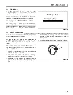
The reel lever linkage actuates two electrical switches
located under the levers. Check that both switches are
closed when all reel levers are in their NEUTRAL
position.
1.
Check and make sure switches are wired correctly.
Refer to Figure 9M and labels attached to wires for
correct terminal placement.
2.
When any of the reel levers are moved to the
forward position, Reel Switch (Wires A and B)
should open, and Backlap Switch (Wires C and D)
should remain closed.
3.
When any of the reel levers are moved to the
reverse position, Backlap Switch (Wires C and D)
should open and Reel Switch (Wires A and B)
should remain closed.
9.15 LEVELING PROCEDURE ___________________________________________________
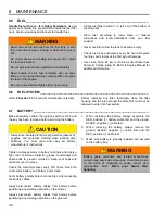
1.
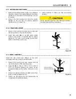
Lower the implements until they are about 1/4 in.
(0.635 cm) above the ground. If they are not level
with the ground, adjust torsion spring (Z).
2.
Carefully loosen spring mounting clamp and slowly
turn clamp until implement is level. Tighten clamp
securely.
Figure 9N
9.16 REEL BEARING ___________________________________________________________
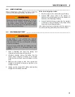
Excessive end play or any radial play indicates bad
bearings, a weak tension spring, or a backed off nut.
1.
Check bearing housing mounting hardware. Tighten
or replace components as required. Carefully clean
threads with degreaser.
2.
Apply a medium strength grade of Loctite to nut
(AA), then thread nut onto the reel shaft until the nut
is 1-27/32 in. (4.6 cm) from the end of the reel
shaft.
3.
Fill reel bearing housings with NLGI - Grade O
grease after adjusting spring.
Figure 9O
A
B
C
D
Reel Switch
Backlap Switch
WARNING
The torsion spring is under extreme tension and will
tend to uncoil very rapidly if the clamp is loosened. To
prevent being cut by clamp or spring, unwind spring
by tapping on clamp while slowly loosening nut.
!
Z
Clamp
GKV-10
GKV-11
AA
AA
1-27/32 in.
(4.6 cm )


