OPERATION AND SERVICE INFORMATION
Page 4
Owner’s Manual and Service Guide
Read all of manual to become thoroughly familiar with this vehicle. Pay particular attention to all Notes, Cautions and Warnings
Depressing the accelerator pedal will release the park
brake if it is engaged. This is a feature to assure the vehi-
cle is not driven with the park brake engaged. Depress-
ing the accelerator pedal is not the preferred method of
releasing the park brake.
Depressing the lower section of the brake
pedal is the preferred method of releasing the
park brake to assure the longest service life of brake compo-
nents.
COMBINATION SERVICE BRAKE AND PARK
BRAKE PEDAL
The brake pedal incorporates a park brake feature (Ref.
Fig. 7 on page 3). To engage, push down on the upper
section of the pedal until it locks in place. The park brake
will release when the service brake pedal is depressed.
Use the lower section of the brake pedal to operate the
service brake system.
OPTIONAL FRONT DISC BRAKES
The front disc brakes activate as the brake pedal
reaches the ‘park’ or latch position. Depressing the brake
pedal further will increase the effectiveness of the front
brakes.
RUN - TOW/MAINTENANCE SWITCH
(PDS VEHICLES ONLY)
To reduce the possibility
of severe injury or death
resulting from loss of
vehicle control, consider the grade of the terrain the
vehicle is on and set vehicle’s park brake accordingly
before switching the Run - Tow/Maintenance switch
to the ‘Tow/Maintenance’ position. When in the ‘Tow/
Maintenance’ position, the Anti-Roll Back and Walk-
Away safety features of the PDS system no longer
function.
Before attempting to tow vehicle, move
the Run-Tow/Maintenance switch to the
‘Tow/Maintenance’ position. Failure to do so will damage the
controller or motor.
Before disconnecting or connecting a battery, or any other wir-
ing, move the Run-Tow/Maintenance switch to the ‘Tow/Mainte-
nance’ position.
After connecting a battery, or any other wiring, wait a minimum
of 30 seconds before moving the Run-Tow/Maintenance switch
to the ‘Run’ position.
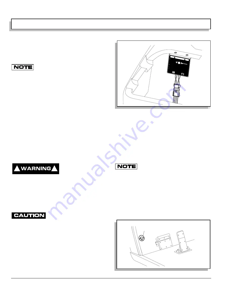
The PDS vehicle is equipped with a two position switch
located under the passenger side of the seat on the con-
troller environmental cover (Ref. Fig. 8 on page 4).
With the switch in ‘TOW/MAINTENANCE’ position:
•
the controller is deactivated
•
the electronic braking system is deactivated which
allows the vehicle to be towed or roll freely
•
the warning beeper is deactivated
With the switch in ‘RUN’ position:
•
the controller is activated
•
the electronic braking system and warning beeper
features are activated
PDS vehicles operate only in the ‘RUN’ posi-
tion.
The PDS is a low power consumption unit but it will drain
the vehicle batteries over a period of time. If the vehicle
is to be stored for a prolonged period of time, the PDS
should be disconnected from the batteries. See ‘Pro-
longed Storage’ on page 23.
HORN
The horn is operated by pushing the horn button located
on the floor to the left of the brake pedal (Ref. Fig. 9 on
page 4).
!
!
Fig. 8 Run-Tow/Maintenance Switch
Fig. 9 Horn Button
TOWING
MAINTENANCE
Always select
'TOW / MAINTENANCE' posit
ion before towing.
After reconnecting batt
eries, allow a mini
mum of 30 secon
ds
before selecting 'RUN' position
To disable electrical system place switch in 'TOW/MAIN
TENAN
CE'
position and remove battery w
ire.
Possibility of electrical arc and battery explosion.
Before removing/connect
ing batteries or electrical components
turn switch to 'TOW/MAIN
TENANCE' position.
RUN
TOW
MAINTENANCE
WARNING
l
73340G01
H
ORN
Horn
PARK
Ref Hor 1
Summary of Contents for Hauler 1000
Page 1: ...ELECTRIC POWERED UTILITY VEHICLES ISSUED APRIL 2005 OWNER S MANUAL AND SERVICE GUIDE 28805 G01...
Page 8: ...Page vi TABLE OF CONTENTS Owner s Manual and Service Guide...
Page 12: ...Owner s Manual and Service Guide SAFETY INFORMATION Page x Notes...
Page 43: ...Page 27 GENERAL SPECIFICATIONS Owner s Manual and Service Guide GENERAL SPECIFICATIONS...
Page 48: ...Page 32 Owner s Manual and Service Guide GENERAL SPECIFICATIONS Notes...
Page 49: ...Page 33 Owner s Manual and Service Guide WARRANTY LIMITED WARRANTIES...
Page 52: ...Page 36 Owner s Manual and Service Guide WARRANTY Notes...
Page 54: ...Page 38 Owner s Manual and Service Guide DECLARATION OF CONFORMITY...
Page 56: ...Page 40 Owner s Manual and Service Guide DECLARATION OF CONFORMITY Notes...
Page 57: ...Appendix A 1 LABELS AND PICTOGRAMS Owner s Manual and Service Guide LABELS AND PICTOGRAMS...


