OPERATION AND SERVICE INFORMATION
Page 18
Owner’s Manual and Service Guide
Read all of manual to become thoroughly familiar with this vehicle. Pay particular attention to all Notes, Cautions and Warnings
Establish the acceptable stopping distance by testing a
new or ‘known to be good’ vehicle and recording the
stopping location or stopping distance. For fleets of vehi-
cles, several vehicles should be tested when new and
the range of stopping locations or distances recorded.
Over time, a subtle loss of performance may
take place; therefore, it is important to establish
the standard with a new vehicle.
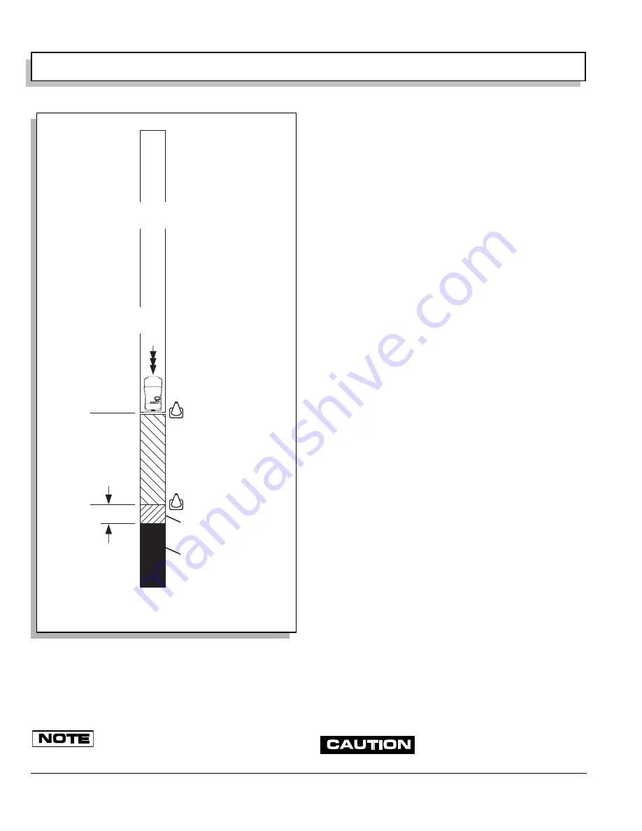
Drive the vehicle at maximum speed on a flat, dry, clean,
paved surface (Ref. Fig. 22 on page 18). Quickly depress
the brake pedal to latch the parking brake at the line or
marker in the test area and remove foot from pedal. The
vehicle should stop aggressively. The wheel brakes may
or may not lock. Observe the vehicle stopping location or
measure the vehicle stopping distance from the point at
which the brakes were latched. The vehicle should stop
within the ‘normal’ range of stopping distances. If the
vehicle stops more than 4 ft. (1.2 m) beyond the accept-
able stopping distance or pulls to one side, the vehicle
has failed the test and should be tested again.
If the vehicle fails the second test, it should immediately
be removed from service. The vehicle must be inspected
by a qualified mechanic who should refer to the TROU-
BLESHOOTING section in the Technicain’s Repair and
Service Manual.
HYDRAULIC FRONT DISC BRAKES
For vehicles equipped with hydraulic front disc brakes,
check master cylinder fluid annually or if there is a
decrease in braking effectiveness. Inspect components
for damage or wear. It is unlikely that fluid will need to be
added, unless there is a leak in the system. Raise the
front of the vehicle (See raising the vehicle). Remove
passenger side wheel/tire. Carefully wipe off dirt and
debris from master cylinder and cap before opening.
Remove the cap. Using a mechanics mirror, check to see
that fluid is no more than 1/4” below top of reservoir. Add
DOT 3 or 4 fluid as required.
REAR AXLE
The rear axle is provided with a lubricant level check/fill
plug located on the bottom of the differential. Unless
leakage is evident, the lubricant need only be replaced
after five years.
Checking the Lubricant Level
Clean the area around the check/fill plug and remove
plug. The correct lubricant level is just below the bottom
of the threaded hole. If lubricant is low, add lubricant as
required. Add lubricant slowly until lubricant starts to
seep from the hole. Install the check/fill plug. In the event
that the lubricant is to be replaced, vehicle must be ele-
vated and the oil pan removed or the oil siphoned
through the check/fill hole (Ref. Fig. 23 on page 19).
LUBRICATION
Do not use more than three (3) pumps
of grease in any grease fitting at any
Fig. 22 Typical Brake Performance Test
Latch
Parking Brake
and Take Foot
Off Pedal
Line or Marker
Acceptable
Stopping
Distance
Normal Range of
Stopping Distance
Any vehicles that stop
more than 4 ft. (1.2 m)
beyond the Acceptable
Stopping Distance or
pulls to one side should
be removed from service
and inspected by a
qualified mechanic
Accelerate To
Maximum Speed
4 ft. (1.2 m)
Line or Marker
Dry, Level, Clean, Paved Surface
Ref Bpt 1
Summary of Contents for Hauler 1000
Page 1: ...ELECTRIC POWERED UTILITY VEHICLES ISSUED APRIL 2005 OWNER S MANUAL AND SERVICE GUIDE 28805 G01...
Page 8: ...Page vi TABLE OF CONTENTS Owner s Manual and Service Guide...
Page 12: ...Owner s Manual and Service Guide SAFETY INFORMATION Page x Notes...
Page 43: ...Page 27 GENERAL SPECIFICATIONS Owner s Manual and Service Guide GENERAL SPECIFICATIONS...
Page 48: ...Page 32 Owner s Manual and Service Guide GENERAL SPECIFICATIONS Notes...
Page 49: ...Page 33 Owner s Manual and Service Guide WARRANTY LIMITED WARRANTIES...
Page 52: ...Page 36 Owner s Manual and Service Guide WARRANTY Notes...
Page 54: ...Page 38 Owner s Manual and Service Guide DECLARATION OF CONFORMITY...
Page 56: ...Page 40 Owner s Manual and Service Guide DECLARATION OF CONFORMITY Notes...
Page 57: ...Appendix A 1 LABELS AND PICTOGRAMS Owner s Manual and Service Guide LABELS AND PICTOGRAMS...


