SAFETY, OPERATORS & MAINTENANCE MANUAL
en-57
9
ADJUSTMENTS
B
C
A
E
D
Blades may be sharpened by filing or grinding. When
sharpening, maintain blade balance within 19.4 g/cm.
Failure to keep the blade balanced causes excess
vibration, blade wear and shortened blade life, and
may harm other mechanical components of the
machine as well.
To check blade balance
1.
Determine if there is a lighter end.
2.
Attach a 3.9g weight to the lighter end 127mm
from the centre of the blade.
3.
If the blade is adequately balanced, the weight
should convert the light end into the heaviest
end. If correction is required, file or grind the
heavy end to obtain balance.
NOTES:
•
Do not overheat or weaken blades when
sharpening.
•
Do not straighten bent blades.
*
If the lift portion of the blade is worn thin,
replace with a new blade.
•
Replace cracked or bent blades.
•
For greatest safety always use genuine
replacement blades.
9.6
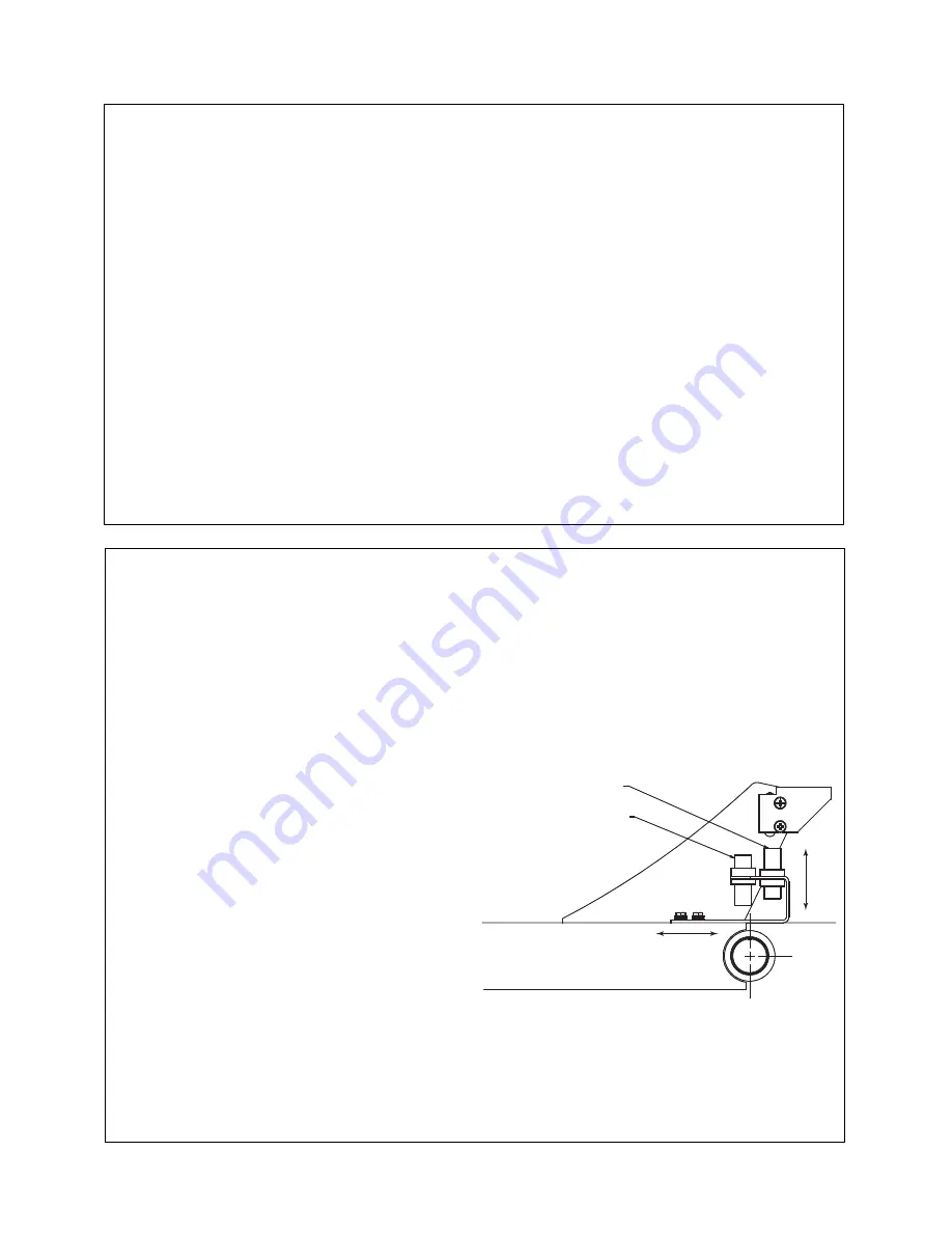
LIFT ARM PROXIMITY SWITCH
Purpose
The magnetic proximity switch activates and
deactivates the cutting circuit.
Location
The magnetic proximity switch is located within the
front axle weldment above the right hand side lift arm
near to its pivot point.
Setting
In general do not adjust the position of the proximity
switch, only the magnets. Once factory set, the switch
should not require further adjustment.
If the magnetic proximity switch requires adjustment
only the magnets should be repositioned.
The magnet closest to the lift arm pivot controls the
lowering of the lift arm and the magnet closest to the
deck controls the raising of the lift arm.
Adjusting the magnet mounting bracket gives course
adjustment, fine adjustment is via the individual
magnet threads.
NOTE: Adjustment should only be undertaken using
the proximity switch test box Ransomes Jacobsen
part number 4168600.
Ensure that after any adjustment the blade drive
disengages when any part of the blade is raised above
400mm and does not restart until all parts of the blade
are below 400mm.
NOTE: If a magnet is lost from the bracket, the
proximity sensor will not be activated. The system is
designed to fail safe resulting in none activation of the
cutting circuit.
A.
Magnetic Proximity Switch
B.
Lower Magnet
C
Raise Magnet
D.
Course Adjustment
E.
Fine Adjustment
Summary of Contents for HR3300T
Page 2: ...2011 Ransomes Jacobsen Limited All Rights Reserved...
Page 43: ...SAFETY OPERATORS MAINTENANCE MANUAL en 43 7 OPERATION...
Page 79: ...en 79 12 QUALITY OF CUT...
Page 84: ......
Page 85: ......


