background image

MAINTENANCE 9

en-44

9.14 SHARPENING BLADES _____________________________________________________

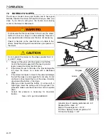
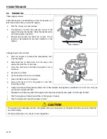
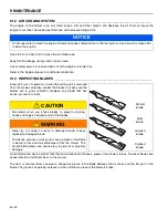
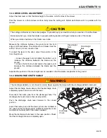
Put a wooden block between the blade and cutting unit housing 
to prevent the blade to rotate.

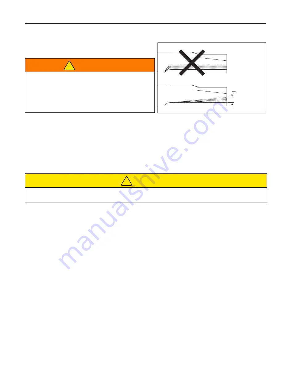
When you prepare or sharpen the blade, do not follow the original grind pattern. Grind new cutting edges at an angle. If 
the maximum of one half inch (1.3 cm) blade loss has occurred, do not sharpen more, replace the blade.

To prevent a blade that is not balanced, make sure an equal amount of material is removed from both ends of the 
blades. A blade that is not balanced will cause vibration and can damage the mower. Use a blade balancer to check the 
blade after you sharpen.

Torque center blade bolt to 125-135 ft.Lb. (169 to 183 Nm).

9.15 ELECTRICAL SYSTEM

____________________________________________________________

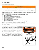
General precautions to decrease electrical problems are -

Make sure that all the connections are clean and correctly fastened.

Check the OPC system, fuses and circuit breakers at normal intervals. If the OPC system does not operate 
correctly and you can not correct the problem, contact an authorized Jacobsen Dealer.

Keep the wiring harness away from hot surfaces and moving parts.

Check the battery and the alternator.

Do not wash or pressure spray around electrical connections and components.


WARNING

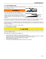
The cutting unit blades can have sharp edges. To prevent 
injury, use caution when you service or hold the blade.

When you remove more than one half inch of material, the 
blade tip can break and be discharged from the mower. The 
broken blade pieces can cause injury to persons or property 
damage.


CAUTION

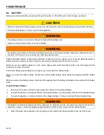
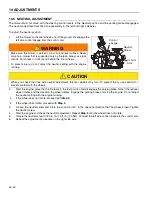
Always turn the ignition switch to the off position and remove the negative (BLACK) battery cable before you inspect 
or service the electrical system.

Maximum 
1/2 in.

(1.3 cm)

!

!

Summary of Contents for Standing Zero Turn Rotary Mower SZT 2648

Page 1: ... and maintain this machine should be trained in its proper use warned of its dangers and must read the entire manual before attempting to set up operate adjust or service the machine GB Standing Zero Turn Rotary Mower ZT90023 SZT 2648 48 Inch 121 9 cm Cutting Unit ZT90024 SZT 2654 54 Inch 137 2 cm Cutting Unit 700507 Rev A ...

Page 2: ...quirements 35 Maintenance 9 1 General Precautions 36 9 2 Engine 36 9 3 Engine Oil 37 9 4 Engine Air Filter 38 9 5 Fuel 38 9 6 Battery 39 9 7 Charge the battery 40 9 8 Engine Exhaust 40 9 9 Drive Axle Fluid 41 9 10 Tires 42 9 11 Wheel Mounting Procedure 42 9 12 Air Cooling System 43 9 13 Inspecting Blades 43 9 14 Sharpening Blades 44 9 15 Electrical System 44 9 16 Care and Cleaning 45 9 17 Mower St...

Page 3: ...cut the grass and not for any other purpose Compliance with the conditions or operation service and repair specified by the manufacturer are understood to be part of the correct use ALL operators MUST read through this manual and understand the Safety Instructions controls lubrication and maintenance procedures Make sure that you obey all safety and road traffic regulations You must not make any c...

Page 4: ...tion Numbers The engine Model Type and Code numbers are stamped on the top of the right side valve cover The engine serial number is also found on a label on the side of the engine 2 3 SERIAL NUMBERS ________________________________________________________ Record the mower and engine numbers shown below Mower Number _________________________ Engine Number __________________________ MMMMMMMSSSSSS B...

Page 5: ... use all of the necessary lifting equipment Use the correct tools and Personal Protective Equipment PPE and take instruction from the technical manuals applicable to the mower Remove and keep correctly 1 Batteries 2 Fuel 3 Engine coolant 4 Oils Disassemble the structure of the mower and refer to the technical manuals Give attention to parts that have mechanical pressure or tension applied to the p...

Page 6: ...nect or prevent the operation of any switch c Never operate equipment that is not in correct order or without decals guards shields deflectors or other protective devices fastened DO NOT operate the cutting unit without the discharge chute installed d Inspect the mower before you operate the mower Check the tire pressure and the engine oil level Fuel is flammable Use caution when you add the fuel ...

Page 7: ...her hazards that are not visible g When you drive in the reverse direction look behind you and down to make sure the path is clear Do not operate the cutting unit when you drive in the reverse direction h Use caution when you go near corners trees or other objects that can prevent a clear view i Equipment must meet the current regulations to be driven on the public roads j Before you move across o...

Page 8: ... surface c Never work on a mower that is lifted only by the jack Always use the jack stands d Never allow persons to service the mower or its attachments without correct instructions e When the mower is parked put into storage or left without an operator lower the cutting device unless a positive mechanical lock is used f When you put the mower on a trailer or put the mower in storage close the fu...

Page 9: ...the battery before you weld on this mower 3 1 6 WHEN YOU PUT THE MOWER ON A TRAILER a Be careful when you load or unload the mower on a trailer Trailer must be wider than the mower and can carry the weight of the mower b Use a full width ramp to load or unload the mower on a trailer c Use straps chains cables or ropes to fasten the mower to the trailer Both front and rear straps must be sent down ...

Page 10: ...thorized Jacobsen Dealer Your Dealer knows the current methods to service this equipment WARNING The OPC System on this mower prevents the operation of the mower unless a The parking brake is engaged b The PTO switch is in the OFF position and c The steering control levers are in the Neutral position The system will stop the engine if the operator leaves the operator position without a The parking...

Page 11: ...9 kW 3600 RPM Compression Ratio 8 4 1 Maximum Speed 3650 100 rpm No Load Low Idle 1750 100 rpm No Load Rotation Clockwise viewed at flywheel Fuel System 2 Barrel Float Feed Carburetor Fuel 87 Octane Gasoline Maximum 10 Ethanol Injection System Magnetron Spark Plug Gap 0 030 Inch 0 76 mm Engine Oil API Class SF SG SH SJ or higher Oil Pan Capacity 2 06 to 2 12 quarts 1 95 to 2 01 l Starter 12 Volt S...

Page 12: ...rm Down 79 inch 200 7 cm F Total length Platform Lifted 67 5 inch 171 4 cm G Wheel Base 49 inch 124 5 cm H Front Wheel Track 34 inch 86 4 cm J Rear Wheel Track 37 inch 94 0t cm Weight of unit 1087 lb 493 1 kg 1110 lb 503 5 kg Tire Specifications Rear Wheel SZT 2648 Rear Wheel SZT2654 Tire Size Type Tire Pressure Tire Size Type Tire Pressure 23 x 9 5 12 Grassmaster 8 10 psi 0 55 0 69 BAR 23 x 10 5 ...

Page 13: ...SPECIFICATIONS 4 en 12 F E G A D B A SZT 2654 SZT 2648 D B H J C H J C ...

Page 14: ...ance 3 7 acres hr 1 5 hectares hr 8 mph 12 87 km hr 4 4 CUTTING UNIT SPECIFICATION _____________________________________________ 4 5 BELT SPECIFICATION _____________________________________________________ Traction Belt Part Number 200704 A Section Raw A56 57 97 EL Belt SZT 2648 Deck Belt Part Number 301160 B Section Wrapped 123 82 EL Belt SZT 2654 Deck BeltPart Number 301253 B Section Wrapped 136...

Page 15: ...________________________________________________________ Product number TBD 4 8 2 MULCHING KIT____________________________________________________________ 48 Inch 121 2 cm Cutting Unit Kit Number 902997 54 Inch 137 2 cm Cutting Unit Kit Number 902996 4 8 3 ACCELERATOR BAGGER___________________________________________________ Kit Number TBD 4 9 SUPPORT LITERATURE ___________________________________...

Page 16: ...ownward position when vulnerable objects or property are in the vicinity of the machine during operation 97072 DANGER MAXIMUM TONGUE WEIGHT 100 lbs WARNING 800208 Serious injury or death can result from blade contact or from contacting the belts or pulleys with the engine running Deck spindles may have a fan installed above or below the pulleys Do not operate the mower with the discharge chute or ...

Page 17: ...operate the mower Pick up sticks stones and other debris that can be thrown by the mower Wear eye protection when you operate the mower Wear ear protection when you operate the mower Keep bystanders away from the mower Be careful of debris thrown by the mower Use caution when you operate on slopes Only operate on slopes with the ROPS in the vertical position Do not carry passengers 800848 DO NOT O...

Page 18: ...______________ 4 25 4 3 5 3 75 3 25 3 2 5 2 75 2 25 2 1 75 1 5 800900 4 5 NEUTRAL RELEASE 800691 800692 800846 PARKING BRAKE 800844 Fast Reverse Slow Reverse Slow Forward Fast Forward Neutral Steering Control Lever Engaged Position Disengaged Position Fast Slow Engine Throttle ...

Page 19: ...CONTROLS 6 en 18 6Controls 6 1 MOWER CONTROLS _______________________________________________________ 6 2 6 4 6 3 ...

Page 20: ...______________ 6 2 1 IGNITION SWITCH _________________________________________________________ The ignition switch has three positions OFF RUN and START N N E F 1 2 FUEL STOP CHOKE 6 2 1 6 2 2 6 2 3 6 2 4 6 2 5 6 2 6 6 2 7 6 2 7 6 2 8 6 2 8 6 2 9 6 2 10 6 2 11 STOP OFF RUN START ...

Page 21: ...EL GAUGE _____________________________________________________________ The fuel gauge shows the hours of operation and the level of fuel The hour meter in the center of the gauge shows the hours of operation of the mower When the ignition switch is in the RUN position the hour meter is active The fuel gauge is above the hour meter The fuel gauge shows the level of fuel in the tank Do not allow the...

Page 22: ..._____________ The 12 Volt accessory outlet supplies power to 12 Volt accessories Only use the 12 Volt outlet with the engine started to prevent a drained battery NOTICE The choke control is not necessary to start a warm engine CAUTION The 12 Volt accessory outlet is protected by a 10 Amp fuse Do not use attachments with a power rating greater than 120 watts To prevent the risk of burns or fire do ...

Page 23: ...g control levers must be pushed in the forward or reverse direction for the cutting units blades to rotate 6 2 9 PARKING BRAKE__________________________________________________________ The parking brake locks the steering control levers in the Neutral position to prevent movement of the mower When the steering control levers are in the Neutral position pull the parking brake lever to the engaged p...

Page 24: ...charge chute located beneath the discharge deflector When you mow around flower beds or edges of paths the discharge chute can be closed to limit the discharge Never mow with the discharge deflector removed NOTICE To prevent damage to the HOC pin or the cutting unit slowly lower the lever against the HOC pin Do not allow the cutting unit to drop from the lifted position against the HOC pin WARNING...

Page 25: ... the operator walking behind the mower When the operator walks behind the mower the operator platform must be lifted Lift the rear part of the platform until the platform is held by the latch To lower the platform hold the platform with one hand and lift the latch Slowly lower the platform WARNING The mower wheels will turn with the neutral release knobs in the release position and the parking bra...

Page 26: ...ke sure that all hoses are in good condition Check the fuel supply and crankcase oil level When the engine is cold all fluids must be at the full level mark Check the engine oil cooler fins for dirt or grass Clean with compressed air as required before you operate the mower Check all tires for the correct pressure Test the OPC system CAUTION The inspection must be done each day when the engine is ...

Page 27: ...urn off the engine between each test TEST 1 The test shows the normal engine start procedure The operator is on the platform parking brake is engaged the steering control levers are in the NEUTRAL position and the PTO switch is in the OFF down position The engine will start TEST 2 The engine must not start if the PTO switch is in the ON position TEST 3 The engine must not start if the parking brak...

Page 28: ...operty 8 Be careful when you operate near to gravel areas roads parking areas cart paths Stones released from the equipment can cause injuries to persons and cause damage to the equipment 9 When you are not mowing grass always turn off the PTO switch 10 Before you move across or operate on the paths or roads turn off the PTO switch lift the cutting unit and travel at decreased speed Look for traff...

Page 29: ...Allow the engine to become warm before you operate the engine at full throttle 7 5 TO STOP THE ENGINE _____________________________________________________ To stop and park the mower in normal conditions 1 Turn the PTO switch to the OFF position Drive the mower to a flat and level area to park the mower 2 Remove your hands from the steering control levers 3 Lower the cutting unit to the ground Eng...

Page 30: ...r the maximum reverse speed To turn the mower to the left push the right side drive lever more than the left side drive lever The greater the difference in lever position the sharper the mower will turn To do a zero radius left turn press the right side lever toward the forward stop and pull the left side lever toward the reverse stop To turn the mower to the right push the left side drive lever m...

Page 31: ...ers forward to drive the mower Never mow in the reverse direction 4 Slow down when you turn the mower or mow on slopes HOC HOC Hole Hole 1 1 1 2 Inch 3 8 cm 8 3 1 4 Inch 8 3 cm 2 1 3 4 Inch 4 4 cm 9 3 1 2 Inch 8 9 cm 3 2 Inch 5 1 cm 10 3 3 4 Inch 9 5 cm 4 2 1 4 Inch 5 7 cm 11 4 Inch 10 2 cm 5 2 1 2 Inch 6 4 cm 12 4 1 4 Inch 10 8 cm 6 2 3 4 Inch 7 0 cm Fully Raised 4 1 2 inch 11 4 cm 7 3 Inch 7 6 c...

Page 32: ...bottom of a slope with a high angle lower the cutting unit to the ground This procedure makes sure the mower does not turn upside down 5 Correct tire pressure is necessary for maximum traction Rear 8 10 psi 0 55 0 69 BAR WARNING To make sure that the mower does not turn over the safest method to drive on a slope is to drive vertically Travel at a slow speed and do not make turns that are not neces...

Page 33: ...es with 1 Yard Level A Millimeters with 1 Meter Level A Slope in Degrees Slope Grade 3 4 8 8 3 100 5 7 10 0 150 8 5 15 6 9 5 16 7 200 11 3 20 0 7 5 11 8 20 8 225 12 7 22 5 9 250 14 25 0 275 15 4 27 5 10 15 5 27 8 300 16 7 30 0 11 17 0 30 6 325 18 0 32 5 12 18 4 33 3 350 19 3 35 0 13 19 9 36 1 375 20 6 37 5 14 21 3 38 9 400 21 8 40 0 15 22 6 41 7 425 23 0 42 5 16 24 44 4 475 25 4 47 5 18 500 26 6 5...

Page 34: ... on the trailer Engage the parking brake If the trailer is moved on the highway inflate the tires to the maximum pressure recorded on the tire before you fasten the mower to the trailer Decrease the tire pressure after the mower is removed from the trailer Disengage the parking brake Before towing disengage the parking brake and make sure the cutting unit is lifted When the mower gets to the servi...

Page 35: ...k fuel lines and fittings Inspect parking brake and steering control lever linkage Inspect deck and drive belts Check for loose components Lubricate grease fittings See 9 5 See 8 2 First 75 Hours Replace drive axle fluid and filter Two per mower See 9 9 Each Two weeks 100 Hours Clean or replace air filter Check engine exhaust system Replace engine oil and filter See 9 4 See 9 8 See 9 3 Each month ...

Page 36: ... ____________________________________________________ Fluid Requirements Quantity Type Engine Oil with Filter 2 06 to 2 12 quarts 1 95 to 2 01 l SAE 10W 30 API Classification SJ Drive Axle with Filter 2 41 quarts 2 28 liter Each 2 Per Mower SAE 20W 50 API Classification SL Fuel 6 U S Gallons 22 7 l 87 Octane Gasoline Maximum 10 Ethanol 1 1 2 ...

Page 37: ...ufacturer Read the Engine Manual and know the operation and maintenance of the engine When you follow the engine manufacturer instructions you will make sure of the maximum service life of the engine The replacement engine manuals are available from the engine manufacturer The operation and maintenance during the first 5 hours of a new engine can make a difference to the performance and life of th...

Page 38: ... oil drain cap c Lower the drain hose and drain the engine oil into a container d Remove the oil filter e Let the engine oil flow into a container f Clean the filter area on the engine g Apply a thin layer of oil to the gasket on new filter Install the oil filter h Tighten the filter until the gasket contacts the oil filter adapter then tighten an additional 1 2 to 3 4 turn Only use your hand to t...

Page 39: ...he mower Only use an approved container The spout on the container must fit inside the fuel filler neck Never use the containers that are not approved to keep or transfer fuel Fill the fuel tank to the bottom of the filler neck Do not use premium gasoline or an oil gasoline mixture Use clean fresh regular unleaded gasoline 85 octane minimum When using blended fuel do not use a blend with more than...

Page 40: ... to jump start the mower check the condition of the drained battery b Connect the positive battery terminal of the charged battery to positive battery terminal of the drained battery c Connect the negative battery terminal of the charged battery to frame of vehicle with the drained battery d When the cables are connected start the engine on the vehicle with the good battery then start the mower CA...

Page 41: ... sound of the exhaust stop the engine immediately Identify the problem and have the system repaired Torque all exhaust manifold hardware equally Tighten or replace the exhaust clamps WARNING Charge the battery in an area with good airflow The battery can release hydrogen gas that is explosive To prevent an explosion keep any device that can cause sparks or flames away from the battery When the bat...

Page 42: ... Assemble the expansion bottle cap h Repeat steps a f for the other drive axle After the drive axle fluid is changed the air must be removed from the drive axles Lift the rear wheels off the ground Support the mower with jack stands a Start the engine and disengage the parking brake b Move the neutral release knobs to the Neutral Released position Slowly move the steering control levers from the N...

Page 43: ...t the wheel to make sure of full contact between surface of wheel and hub Tighten all hardware with your fingers then torque hardware in a criss cross order When possible tighten nuts in the top position Check and torque hardware each day until torque is kept at 65 75 ft lb 88 102 Nm CAUTION DO NOT try to put a tire on a rim unless you have the correct training tools and experience Incorrect mount...

Page 44: ...at has bends grooves or cracks A bent blade can have a small crack that can increase and cause a piece of the blade to break The bent blades can cause vibration and other stress on the mower The dust or sand particles can wear a dangerous groove in the blade between the air vanes and the flat part of the blade The groove can quickly increase in size and allow a piece of the blade to break NOTICE D...

Page 45: ..._________________ General precautions to decrease electrical problems are Make sure that all the connections are clean and correctly fastened Check the OPC system fuses and circuit breakers at normal intervals If the OPC system does not operate correctly and you can not correct the problem contact an authorized Jacobsen Dealer Keep the wiring harness away from hot surfaces and moving parts Check t...

Page 46: ...cleaners To keep the original high polish of the fiberglass parts wax with a good grade of one step cleaner wax Repair damaged metal surfaces and use Jacobsen touch up paint Apply wax to the equipment for maximum paint protection NOTICE Do not wash any part of the mower that is hot Do not use the high pressure spray or steam Use cold water and automotive cleaners NOTICE To use salt water or drain ...

Page 47: ...e the engine oil and filter Clean the outside surface of the engine Paint bare metal or apply a thin layer of rust preventative oil Add a fuel stabilizer to prevent the fuel to become stale See your fuel supplier for instructions Start the engine Operate the engine for two minutes to circulate the stabilizer throughout the fuel system Cutting Units Completely clean the cutting units Repair and pai...

Page 48: ...res 10 2 FORWARD SPEED ADJUSTMENT____________________________________________ The cutting quality is improved at speeds lower than the full transport speed of the mower The local turf condition may require a different speed To adjust the forward speed adjust the speed limit screws in the control panel Turn the screws to the right side to decrease the forward speed Turn the screws toward the left s...

Page 49: ...ARGE CHUTE CABLE ______________________________________________________ Adjust the discharge chute cable so that the discharge chute completely opens and closes with the lever Disconnect the cable yoke from the discharge chute The discharge chute will move to the closed position Push the discharge chute lever forward to the closed position Adjust the cable yoke until the clevis pin can be installe...

Page 50: ... rotate proceed with Step 5 b If the wheel does rotate proceed with Step 3 3 Loosen the neutral screw and rotate the control arm 5 in the opposite direction that the wheel turned Tighten the neutral screw 4 Start the engine and check the neutral adjustment Repeat Step 3 until the wheel does not rotate 5 Torque the neutral screw to 180 in lb 15 ft lb 20 Nm Connect the left side control linkage to t...

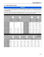
Page 51: ...209 1 4 20 in lb Nm 75 8 4 100 11 3 107 12 1 143 16 1 9 16 18 ft lb Nm 92 124 122 165 129 174 172 233 1 4 28 in lb Nm 85 9 6 115 13 0 120 13 5 163 18 4 5 8 11 ft lb Nm 113 153 151 204 159 215 211 286 5 16 18 in lb Nm 157 17 7 210 23 7 220 24 8 305 34 4 5 8 18 ft lb Nm 128 173 170 230 180 244 240 325 5 16 24 in lb Nm 173 19 5 230 26 0 245 27 6 325 36 7 3 4 10 ft lb Nm 200 271 266 360 282 382 376 50...

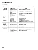
Page 52: ... to start or runs poorly 1 Fuel level low fuel or fuel filter dirty 1 Fill with fresh fuel Change fuel filter 2 Air cleaner dirty 2 Inspect and replace air filter 3 Engine problem 3 Consult engine manual Engine stops 1 Fuel tank empty 1 Fill with fresh fuel and bleed fuel lines 2 Interlocks not set before leaving operator s position 2 Engage parking brake and set power take off switch to OFF Engin...

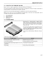
Page 53: ...ARDING__________________________________________________________ NOTE Arrow indicates direction of travel Washboarding is a repeated pattern of different cutting heights that causes an appearance that is like a wave In most cases the wave tip to tip distance is approximately 6 8 in 15 20 cm A change in the color from light to dark is also seen This cause of this condition can be a movement from si...

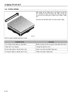
Page 54: ...an occur when one cutting unit is higher than another cutting unit The wear of mechanical parts can cause step cutting Probable Cause Remedy The cutting unit movement is prevented Check and remove the cutting unit movement obstruction Differences in turf density Change the direction of cut Mower ride height is uneven side to side Check and adjust tire inflation pressure Cutting unit height is unev...

Page 55: ...rea can be light green or brown A low HOC setting or turf that is not level can cause scalping Probable Cause Remedy HOC height of cut set is lower than normal Check and adjust the HOC See 7 7 Turf is not level and the mower can not follow the turf Change the direction of cut Grass is higher than the cutting unit capacity Cut the grass more frequently Cut ground speed is higher than the mower can ...

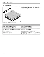
Page 56: ...se Remedy Edge of the cutting blade s are not sharp Sharpen the blade s See 9 14 Cut ground speed is higher than normal Reduce the cut ground speed The grass is higher than the level at which the mower can cut correctly Cut the grass more frequently Cut in the same direction Change the direction of cut more frequently The blade speed is too slow Operate the mower with the engine at full throttle I...

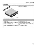
Page 57: ... a streak can be a damaged blade Probable Cause Remedy Damaged blade s Replace the blade s See 9 13 The tires compresses the grass before the grass is cut Check and adjust the tire inflation pressure The blades are not installed correctly Check to make sure the correct blade is installed on each motor The mower compresses the wet grass before the grass is cut Cut the grass when grass is dry TN0224...

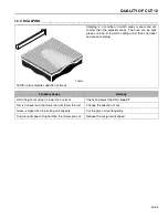
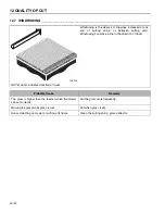
Page 58: ...sed at one end of cutting unit s or between cutting units Windrowing can make a line in the direction of travel Probable Cause Remedy The grass is higher than the level at which the mower can cut correctly Cut the grass more frequently Mowing the grass while grass is wet Cut when grass is dry Grass collecting on mower or cutting unit frame Clean the cutting unit s grass deflector TN0225 ...

Page 59: ...NOTES 13 en 58 13Notes ...

Page 60: ...en Performance Matters Equipment from Jacobsen is built to exacting standards ensured by ISO 9001 and ISO 14001 registration at all of our manufacturing locations A worldwide dealer network and factory trained technicians backed by Genuine Jacobsen Parts provide reliable high quality product support ...

Reviews: