background image

en-40

JACOBSEN TR3

SAFETY, OPERATORS & MAINTENANCE MANUAL

8.7

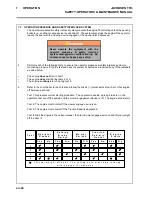
HYDRAULIC SYSTEM

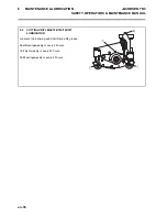
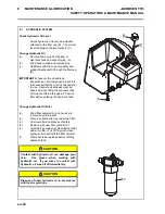
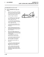
Check Hydraulic Oil Level

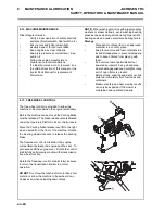
Check hydraulic oil level using dipstick 
attached to the filler cap (B).  The correct 
level is between the two markers (C).

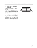
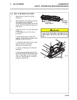
Change Hydraulic Oil
(a)

Remove drain plug from bottom of 
Hydraulic tank and wipe off plug. (A)

(b)

Allow tank to drain and replace plug.

(c)

Refill tank with the correct quantity and 
grade of Hydraulic Oil through the filler cap. 
(B) .

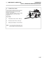
IMPORTANT-Whenever the closed loop 

transmission circuit has been broken into, 
it is essential that the circuit is flushed prior 
to use.  Absolute cleanliness must be 
observed when filling the hydraulic tank.  
Oil must be filtered through a 25 micron 
filter before entering the hydraulic tank. 

8

MAINTENANCE & LUBRICATION

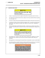
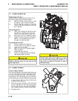
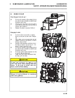
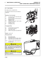
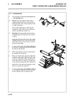
Change Hydraulic Oil Filter

(a)

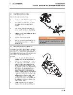
Wipe filter canister (A) and housing to 
remove any dirt present.

(b)

Place a suitable drip tray under the filter.

(c)

Unscrew filter and dispose of safely.

(d)

Replace with new filter canister (A).

(e)

Coat the top outside lip of the filter canister 
with a thin film of oil, fill filter with clean 
hydraulic fluid and refit the filter canister.

(f)

Filter should be replaced before refilling 
hydraulic tank.


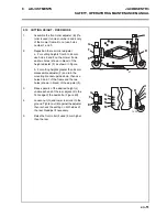
CAUTION

Contact with hydraulic oil can damage your
skin.  Use gloves when working with
hydraulic oil.  If you come in contact with
hydraulic oil, wash it off immediately.


CAUTION

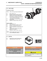
Dispose of used hydraulic oil in accordance
with local regulations.

Summary of Contents for TR3 EJ Series

Page 1: ...in its proper use warned of its dangers and should read the entire manual before attempting to set up operate adjust or service the machine GB United Kingdom RJL 100 February 2010 Series EJ 26 Cutting...

Page 2: ...2010 Ransomes Jacobsen Limited All Rights Reserved...

Page 3: ...8 7 5 STARTING THE ENGINE 29 7 6 DRIVING 29 7 7 MOWING 29 7 8 TO STOP THE ENGINE 29 7 9 MOWING ON SLOPES 30 8 MAINTENANCE LUBRICATION 8 1 MAINTENANCE LUBRICATION CHART 34 8 2 CUTTING UNIT LMAC194 195...

Page 4: ...this manual and make themselves thoroughly conversant with Safety Instructions controls lubrication and maintenance Accident prevention regulations all other generally recognized regulations on safety...

Page 5: ...nd Personal Protective Equipment PPE and take guidance from the technical manuals applicable to the machine Remove and store appropriately 1 Batteries 2 Fuel residue 3 Engine coolant 4 Oils Disassembl...

Page 6: ...rs mow only in daylight or good artificial light Always observe the Highway Code both on and off the roads Keep alert and aware at all times Watch out for traffic when crossing or near roadways Stop t...

Page 7: ...ing cylinders Make sure that other people are not touching any cutting units as rotation of one cylinder can cause the others to rotate To reduce the fire hazard keep the engine silencer and battery c...

Page 8: ...g lift levers whilst seated in the driving position 3 Disengage drives stop the engine and make sure all moving parts are stationary Apply brakes and remove the starter key 4 Transport latches can now...

Page 9: ...RD Transport 0 14 km h 0 8 5 mph FORWARD Reverse 0 6 km h 0 3 7 mph Steering Hydrostatic power steering with adjustable tilt steering wheel Ground pressure 1 kg cm2 14p s i Brakes Hydrostatic braking...

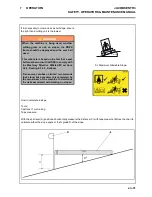
Page 10: ...the normal operating position with both hands on the steering mechanism Thecuttingdevice was rotating with the machine driven in a straight line at 6 Km hr on a level freshly cut lawn The Machinery Sa...

Page 11: ...bricators 4 7 RECOMMENDED LUBRICANTS Engine oil Should be to MIL L 2104C or to A P I Classification CD grades 10W 30 Hydraulic Oil Greenscare 46 ISO 46 Bio Degradable Oil Grease Shell Darina R2 or equ...

Page 12: ...arviointi Evaluation de conformit Konformit tsbeurteilung Megfelel s g rt kel s Valutazione della conformit Atbilst bas nov rt jums Atitikties vertinimas Livell tal Qawwa tal oss Imkejjel Ocena zgodno...

Page 13: ...dtekening van de persoon die bevoegd is de verklaring namens de fabrikant te tekenen de technische documentatie bewaart en bevoegd is om het technische bestand samen te stellen en die is gevestigd in...

Page 14: ...t s iek rtas ra ot ja intelektu l pa uma ties b m Me kohustume riigisiseste asutuste p hjendatud n udmisel edastama asjakohast teavet osaliselt komplekteeritud masina kohta Andmed edastatakse paberkan...

Page 15: ...wyznaczonej ds wsp lnotowych Assinatura da pessoa com poderes para emitir a declara o em nome do fabricante que possui a documenta o t cnica que est autorizada a compilar o processo t cnico e que est...

Page 16: ...o Not Remove Safety Shields While Engine is Running H 009114100 Danger of Explosion if the Battery Terminals are Short Circuited J 009114160 Maximum permissible working slope K 4133706 Caution Diesel...

Page 17: ...Y TO YOU OR OTHERS DO NOT OPERATE THIS UNIT WITH GUARD REMOVED 521720 DANGER Always connect the black ground cable last and remove it first Keep sparks and flames away and avoid contact with acid Conn...

Page 18: ...rake Switch D Cutter Switch E Weight Transfer Switch F Blocked Hydraulic Filter Warning Lamp G Charge Warning Lamp H Engine coolant Temperature Warning Lamp J Engine Oil Pressure Warning Lamp K Contro...

Page 19: ...control panel When the engine is switch off the parking brake is automatically applied To release the parking brake depress the opposite end of the rocker switch DO NOT apply the brake when the machi...

Page 20: ...op up as necessary Check the oil pressure sender switch Continued operation may cause extensive damage to the engine 6 1G CHARGING WARNING LAMP Colour red on when ignition is switched on and will go o...

Page 21: ...single Axis A B A One touch lower Lower all cutting units B Raise all cutting units Needs to be held at position B for lifting units into transport position 6 1L ENGINE PREHEAT INDICATOR LAMP Colour r...

Page 22: ...nd red LED above warning triangle will flash A Clock Function Fuel Gauge Function B Time To Service Function C Total Hours Function Setting the Time Of Day Clock The display will flash the two HOURS d...

Page 23: ...ing brake is set and parking brake light W is lit C Mow Speed Stop Limits forward speed while mowing To operate at lower travel speed while mowing rotate lever so it contactsstop screw D1 onfloorboard...

Page 24: ...Unit Transport Latches are a Secondary Safety Devise When Transporting the machine the Cutting units should be held in the Transport position on the Hydraulics with the Transport Latches Engaged 1 Pa...

Page 25: ...tion 2 Check the fuel supply radiator coolant level crankcase oil level and air cleaner is clean All fluids must be at the full mark with the engine cold 3 Make sure all cutting units are adjusted to...

Page 26: ...marks across the chart Shut engine off between each test Test 1 Represents normal starting procedure The operator is seated parking brake is on the operators feet are off the pedals and the mower eng...

Page 27: ...and or damage to their property 6 Use discretion when mowing near gravel areas roadway parking areas cart paths etc Stones discharged from the implement may cause serious injuries to bystanders and o...

Page 28: ...s are extremely sharp and can cause serious injuries WARNING DO NOT USE ON SLOPES GREATER THAN 15 7 4 FITTING THE CUTTING UNITS TO THE MACHINE 1 With the lift arms in the lowered position slide the cu...

Page 29: ...to start after two attempts with preheat if necessary wait 20 seconds and try again The starter motor should never be run continuously for longer than 30 seconds or it may fail 7 6 DRIVING Release bra...

Page 30: ...nsfer control as required to improve weight distribution between decks and mower 3 If the mower tends to slide or the tyres begin to mark the turf angle mower into a less steep slope until traction is...

Page 31: ...ow across a short slope ensure the right hand cutting unit is the lowest WARNING When the machine is being used whether cutting grass or not on slopes the ROPS frame should be deployed and the seat be...

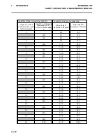
Page 32: ...e D measured in Degrees Slope Angle D measured in Grade 3 4 8 8 3 100 5 7 10 0 150 8 5 15 0 6 9 5 16 7 200 11 3 20 0 7 5 11 8 20 8 225 12 7 22 5 9 250 14 0 25 0 275 15 4 27 5 10 15 5 27 8 300 16 7 30...

Page 33: ...en 33 JACOBSEN TR3 SAFETY OPERATORS MAINTENANCE MANUAL 7 OPERATION...

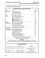
Page 34: ...0 8 10 8 3 8 8 Every 250 hours Change Engine Oil and Oil Filter 8 2 End of season Every 1000 hours Check Battery Condition Change Hydraulic Oil Filter Change Air Filter Element Replace Fuel Filters Ch...

Page 35: ...en 35 JACOBSEN TR3 SAFETY OPERATORS MAINTENANCE MANUAL 8 MAINTENANCE LUBRICATION...

Page 36: ...MANUAL 8 2 CUTTING UNIT LMAC194 195 196 197 LUBRICATION Lubricate the following with Shell Darina R2 grease Reel Bearingsweekly or every 25 hours Unit pivot weekly or every 25 hours Roll bearingsweek...

Page 37: ...se with a manual grease gun and fill slowly until grease begins to seep out Do not use compressed air guns For smooth operation of all levers pivot points and other friction points that are not shown...

Page 38: ...area on crankcase d Apply thin coat of oil to cartridge gasket before installing e Tighten filter by hand only f Check for oil leaks around the cartridge gasket after engine is started CAUTION Dispos...

Page 39: ...se drain cock on engine block A and replace hose back on to radiator Ensure all hose clips are tight c Refill the cooling system with the correct anti freeze mixture see section 9 1 Fill system throug...

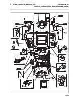
Page 40: ...bserved when filling the hydraulic tank Oil must be filtered through a 25 micron filter before entering the hydraulic tank 8 MAINTENANCE LUBRICATION Change Hydraulic Oil Filter a Wipe filter canister...

Page 41: ...res to be checked All tests unless stated otherwise should be carried out with the hydraulic oil at normal working temperature TEST PORTS A Transmission pressure 210 bar 3045 psi B Deck drive pressure...

Page 42: ...OFF Replace In line fuel C Changing fuel filter a Unscrew filter A from filter head b Remove filter and discard c Fit new filter to head d Bleed air from system as described above 8 MAINTENANCE LUBRIC...

Page 43: ...r a Raise engine cover b Remove end cap of air filter cartridge c Remove accumulated dust or dirt d Remove filter element A pull straight out firmly e install new filter element press firmly against r...

Page 44: ...sually inspect for hydraulic leaks Keep engine bay clear of debris Keep tyre pressure at correct level See section 4 Follow the engine manufacturer s maintenance recommendations If a label becomes wor...

Page 45: ...ng the machine left hand side when viewed from the operating position To adjust 1 Loosen the locknut A whilst holding the threaded shaft still with the Allen Key B 2 Using an Allen key B rotate the th...

Page 46: ...the setting bar G as shown at one end of the bottom blade with the screw head X over the lip and screw thread Y tip against base of blade 4 Adjust the roll to the setting bar G with the two locknuts H...

Page 47: ...heel until it locates in the serrated locking ring The adjuster is of the notched type and each notch is moving the cylinder in increments of approximately 0 04mm 0 0015in THIS IS A SELF LOCKING MECHA...

Page 48: ...bedknife 3 If wear or damage is beyond the point where the reel orbedknife can be corrected by the lapping process they must be re ground or replaced 4 Proper reel to bedknife adjustment is critical A...

Page 49: ...nut C 1 4 turn on both ends of the cutting unit a Turn adjuster A in 1 16 to 1 8 turn increments b Slide a feeler gauge or shim stock 0 025 mm between the reel blade and the bedknife Do not turn the...

Page 50: ...ller to be used The cutting height will range from 9 to 54 mm if a 63 mm solid roller is used or 9 to 57 mm if a 76 mm grooved roller is used 4 To convert the mower from fixed to floating mode remove...

Page 51: ...shown in Figure b For cutting heights greater than 44 mm disassemble adjuster F and turn the mounting bracket upside down then use holes 5 and 7 of the frame and the two holes shown in black of the a...

Page 52: ...andthetwo holes shown inblack of adjuster F 3 Adjust height gauge P to the desired cutting height Loosen nut K and adjust screw L to obtin dimension X then lock nut K against the gauge P 4 Placeoneend...

Page 53: ...sh knob A downwards and allow it to slid back upwards until a comfortable amount of suspension is found B FORE AND AFT ADJUSTMENT To Adjust The position of the adjusting lever is on the left hand side...

Page 54: ...the left hand side oftheseatbelow theseatcushion B By moving the lever upwards the seat can be slid backwards and forwards When in the desired position release the lever to locate in one of the pre se...

Page 55: ...cle components Notes Concerning Seat Switch Minimum and maximum current carrying capacity for purely resistive load In case of inductive or capacitive load the manufacturer must install a protective c...

Page 56: ...re the vehicle is used switches that might be in the seat for shutting down mechanical equipment when the driver leaves his her seat must be checked for proper function If malfunctions are detected th...

Page 57: ...k rest is spring loaded to fold onto the seat cushion Lean back to obtain the desired position for the back rest and release the lever to locate in one of the pre set positions C WEIGHT ADJUSTMENT To...

Page 58: ...material the setting for the driver s weight must be checked and adjusted individually before the vehicle is driven In order to avoid compressor damage during weight adjustment the compressor must be...

Page 59: ...n be turned on off by pressing the switch 1 seat heater OFF 2 seat heater ON 9 19 5 LUMBAR SUPPORT The lumbar support increases both the seating comfort and the performance of the driver By turning th...

Page 60: ...clination of the armrests can be modified by turning the adjustment knob When turning the knob to the outside the front part of the armrest will be lifted when turning the knob to inside it will be lo...

Page 61: ...ning the upholstery should not be soaked through Use a standard commercially available upholstery or plastic cleaning agent Test first for compatibility on a small concealed area WARNING When the mach...

Page 62: ...in the most accessible position for applying the paste Leave the grass boxes in position on the cutting units as a safety barrier Afterapplyingthegrindingpastetheperson backlapping should return to th...

Page 63: ...T LMAC174 A transport latch kit is available for the front lift arms 10 4 WORKING LAMP KIT LMAC163 A Working lamp kit is available to fit two lamps to the front of the operator plateform 10 5 GRASS BO...

Page 64: ...leaner replace as neccesary 3 Injectors fuel pump 3 Consult engine manual 4 Other Engine Problem 4 Consult engine troubleshooting guide Engine Stops 1 Fuel tank empty 1 Fill with fresh fuel and bleed...

Page 65: ...e Alignment to Reel 5 Reel to Bedknife Contact 6 Height of Cut HOC 7 Roller and Roller Bearing Condition 11 2 1 WASHBOARDING NOTE Arrow indicates direction of travel Washboarding is a cyclical pattern...

Page 66: ...of varying cutting heights resulting in a wave like cut appearance In most cases the wave tip to tip distance is 2 in 5 cm or less Probable Cause Remedy Mowing ground speed is too fast Reduce mowing...

Page 67: ...height of cut settings are different from one side of a reel to the other or from one cutting unit to another Check HOC adjustment of cutting units Worn front roller bearings Check replace front rolle...

Page 68: ...ven brown patch This is usually caused by an excessively low height of cut HOC setting and or uneven turf Probable Cause Remedy HOC height of cut settings are lower than normal Check adjust the HOC se...

Page 69: ...se Remedy Bedknife improperly adjusted Adjust reel to bedknife setting Dull reel or bedknife cutting edges Sharpen or replace reel blade and bedknife as necessary Mowing ground speed is too fast Reduc...

Page 70: ...nly w orn reel Inspect reel Replace as needed Loose or missing bedknife fasteners Check bedknife screw s Tighten loose screw s replace missing screw s Turning too aggressively Cutting units don t over...

Page 71: ...eposit of clippings concentrated at one end of cutting unit s or between two cutting units forming a line in the direction of travel Probable Cause Remedy Grass is too tall Mow more often Mowing while...

Page 72: ...tting heights resulting in a stepped cut appearance usually due to mismatched HOC height of cut adjustment from one cutting unit to another Probable Cause Remedy Reel and or bedknife unevenly worn Ins...

Page 73: ...en 73 JACOBSEN TR3 SAFETY OPERATORS MAINTENANCE MANUAL 11 TROUBLESHOOTING...

Page 74: ...en 74 JACOBSEN TR3 SAFETY OPERATORS MAINTENANCE MANUAL 12 1 HYDRAULIC CIRCUIT 12 SCHEMATICS...

Page 75: ...utter Brake Valve 8 Hydraulic Deck Motor 9 Hydraulic Deck Motor 10 Hydraulic Deck Motor 11 Cutter Steering Pump 12 Hydraulic Steering Unit 13 Hydraulic Steering Cylinder 14 Hydraulic Lift Valve 15 Hyd...

Page 76: ...en 76 JACOBSEN TR3 SAFETY OPERATORS MAINTENANCE MANUAL 12 2 ELECTRICAL CIRCUIT INSTRUMENT 12 SCHEMATICS TO SP 19 TO SP 19 2 TO SP 19 B P Y 1 0 1 0 1 TO SP 11...

Page 77: ...ns 1 Fuel Sender 2 IGP 3 Not Used 4 Ground 5 Not Used 6 Set Up Enable 7 Alternator Lamp 8 Battery ve Fuse 63 Joystick Connections 1 SV Input 2 Raise Switch 5 Lower Switch TO 74 1 TO 74 1 TO 2 4 TO 2 4...

Page 78: ...en 78 JACOBSEN TR3 SAFETY OPERATORS MAINTENANCE MANUAL 12 3 ELECTRICAL CIRCUIT MAIN 12 SCHEMATICS...

Page 79: ...Solenoid 12 Engine Oil Pressure Switch 13a Weight Transfer Solenoid 13b Weight Transfer Solenoid 14 Fuel Level Sender 15 Raise Solenoid 16 Seat Switch 17 Accessory Socket 1 18 Accessory Socket 2 19 Hy...

Page 80: ...Start Relay 2 Fuse 7 5 Amp Fuel Pump 3 Fuse 5 Amp Warning Lamps 4 Fuse 5 Amp Warning Lamps 5 Fuse 10 Amp Safety Module 6 Fuse 15 Amp Accessory Socket 1 7 Fuse 15 Amp Accessory Socket 2 8 Fuse 5 Amp W...

Page 81: ...JACOBSEN TR3 SAFETY OPERATORS MAINTENANCE MANUAL 12 4 ELECTRICAL CIRCUIT FUSES AND RELAYS 12 SCHEMATICS FUSES RELAYS In Engine Compartment B Relay Glow Plugs C Strip Fuse 40 Amp Top Cab Bottom Glow P...

Page 82: ...3 0 4 3 4 6 3 6 9 1 1 4 9 5 1 9 8 1 3 4 8 4 4 1 8 3 5 S D A E R H T C N U n i a i D E D A R G A E D A R G S E D A R G T E D A R G V E D A R G X t f f b l t f f b l t f f b l t f f b l t f f b l 4 1 4...

Page 83: ...ied or approved by us for the purpose The use of non recommended oil or lubricant nullifies the guarantee Damage through transport or normal wear does not come under the guarantee The warranty is exte...

Page 84: ......

Page 85: ......
Page 86: ...cobsen Limited West Road Ransomes Europark Ipswich IP3 9TT English Company Registration No 1070731 www ransomesjacobsen com Jacobsen A Textron Company 11108 Quality Drive Charlotte NC 28273 USA www Ja...

Reviews: