en-67
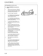
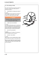
9.18 SEAT (Grammer MSG85)
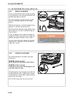
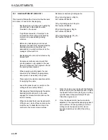
The seat can be adjusted for operator's weight and
leg reach to provide a comfortable position for
operating the machine.
1.
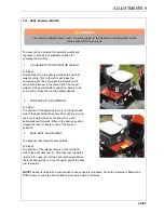
ADJUSTMENT FOR OPERATOR WEIGHT
To Adjust:
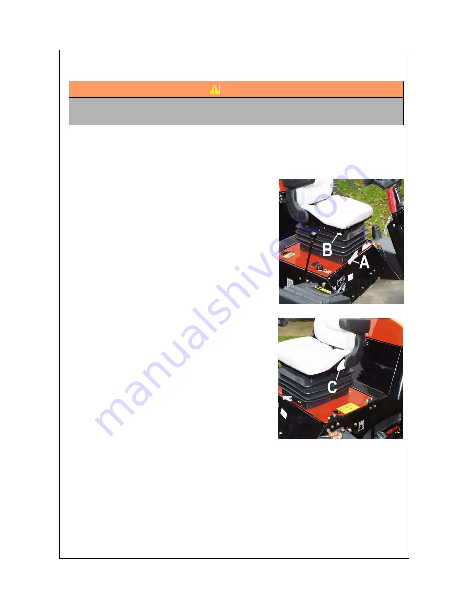
Rotate knob (A) to the right to increase the operator
weight setting. Turn to the left to decrease the
operator weight The set weight is indicated on the
yellow face dial next to the lever. Set at the correct
weight of the operator before operation. Failure to do
so will compromise the machine safety devices.
2.
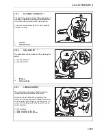
FORE AND AFT ADJUSTMENT
To Adjust:
The position of the adjusting lever is on the right hand
side of the seat below the seat cushion (B). By moving
the lever towards the seat, the seat can be slid
backwards and forwards. When in the desired position
release the lever to locate in one of the pre-set
positions.
3.
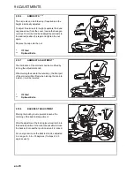
BACK REST ADJUSTMENT
The back rest has three preset positions
To Adjust:
The position of the release lever is on the left hand
side of the seat back rest (C). Move the lever upwards
to move the upper part of the back rest forward. Move
the lever downwards to move the upper part of the back
rest rearwards.
NOTE
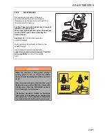
:The seat is fitted with a micro-switch to sense operator presence. When the machine is fitted with a
ROPS frame or cab a lap belt is fitted and should be worn at all times.
WARNING
The Operator Weight must be set to the actual weight of the Operator. Safety Systems will be
compromised if this is not done.
ADJUSTMENTS 9
Summary of Contents for TR3 EJ Series
Page 43: ...en 43 OPERATION 7 NOTES ...
Page 45: ...en 45 MAINTENANCE AND LUBRICATION 8 ...
Page 83: ...en 83 PROBLEM SOLVING 11 NOTES ...
Page 84: ...en 84 12 1 HYDRAULIC CIRCUIT 12 SCHEMATICS ...
Page 88: ...en 88 12 3 ELECTRICAL CIRCUIT MAIN 12 SCHEMATICS ...
Page 135: ...cs 43 OBSLUHA 7 POZNÁMKY ...
Page 137: ...cs 45 LUBRIKACE A ÚDRŽBA 8 ...
Page 175: ...cs 83 ODSTRAŇOVÁNÍ PROBLÉMŮ 11 POZNÁMKY ...
Page 176: ...cs 84 12 1 HYDRAULICKÝ OBVOD 12 SCHÉMATA ...
Page 180: ...cs 88 12 3 VEDENÍ ELEKTRICKÉHO OBVODU 12 SCHÉMATA ...

