background image

34

MAINTENANCE

Read all of SAFETY and this section before attempting any procedure. Pay particular attention to Notices, Cautions, Warnings and Dangers.

Owner’s Guide

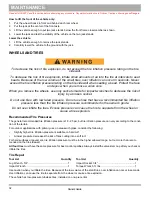
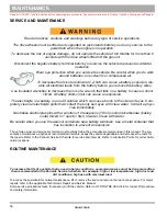
LIGHT BULB REPLACEMENT

To decrease the risk of premature bulb failure, do not allow your fingers to contact new bulbs. Use clean, dry 

paper or paper towels to touch the glass part of the bulb. 

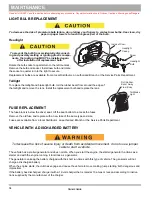
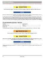
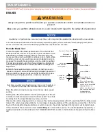
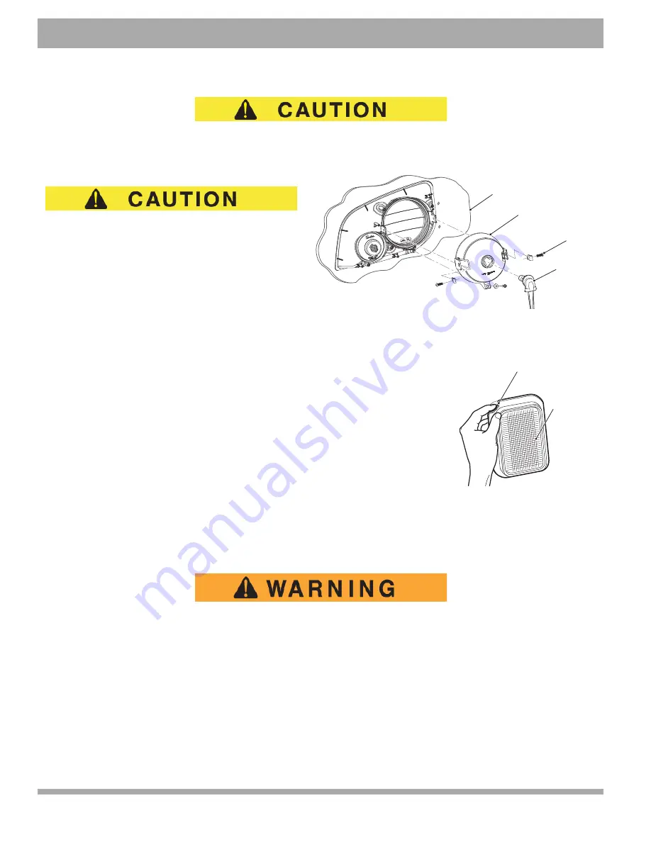
Headlight 

To prevent the bulb from accidentally disconnect-

ing and possibly melting or igniting plastic compo-

nents, the locking ring MUST be installed again 

after installation of replacement bulb.

Rotate the bulb socket a quarter turn to the left to unlock. 
Remove the bulb and socket. Install new bulb and rotate 
the socket a quarter turn to the right to secure.

Replacement bulbs are available from a local Distributor, an authorized Branch or the Service Parts Department.

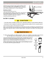
Taillight

To replace the taillight and brake light bulb, roll the rubber bezel from around the edge of 
the taillight and remove the lens. Install the replacement bulb and replace the lens.

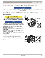
FUSE REPLACEMENT

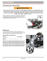
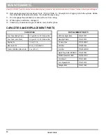
The fuse block is below the driver seat. Lift the seat bottom to access the fuses.

Remove the old fuse and replace with a new fuse of the same type and size. 

Fuses are available from a local Distributor, an authorized Branch or the Service Parts Department.

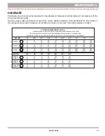
VEHICLE WITH A DISCHARGED BATTERY

To decrease the risk of severe injury or death from accidental movement, do not use a jumper 

cable to start a vehicle.

The vehicle has a starter/generator and does not idle. When you start the engine, the starter/generator functions as a 
starter and with the engine running, it functions as a generator.

The generator can keep the battery charged with the short run times with this type of vehicle. The generator will not 
charge a discharged battery.

When the engine starts, the clutches engage and cause the vehicle to move making ‘jump starting’ both dangerous and 
impractical.

If the battery has discharged, charge it with a 12-volt charger that is rated at 10 amps or less and according to instruc-
tions supplied by the manufacturer of the charger.

Inside of Cowl

Headlight 
Casing

Screw

Headlight
Bulb

Tail/Brake
Light

Roll Rubber
Bezel Away
From Body

Summary of Contents for TRUCKSTER MX

Page 1: ...OWNER S GUIDE 649010 REVISED NOV 2015 ISSUED AUG 2015 TRUCKSTER MX...

Page 2: ...ferences in controls will be illustrated Most of the service procedures in this guide can be accomplished using standard automotive hand tools Contact your ser vice representative for servicing the ve...

Page 3: ...SE QUENTIAL DAMAGES resulting from the use of the information and materials in this manual These are the original instructions as defined by 2006 42 EC CONTACT INFORMATION JACOBSEN A Textron Company 1...

Page 4: ...ntain the United States of America Federal and State emission certification applicable at the time of manufacture BATTERY PROLONGED STORAGE The batteries discharge over time The rate of discharge chan...

Page 5: ...ATURES 11 General Information 11 Steering Wheel 11 Brake Pedal 11 Parking Brake 11 Horn 11 Turn Signal If Equipped 11 Accelerator Pedal 11 Key Light Switch 12 Fuel Gauge with Low Oil Pressure Indicato...

Page 6: ...20 STARTING AND DRIVING 20 Run in 20 Cold start 21 Starting Vehicle On A Hill 21 Coasting 22 FUEL 22 FUEL TANK 23 Early Production Fuel Tank 23 Late Production Fuel Tank 23 BATTERY 24 LABELS AND PICT...

Page 7: ...NCE 36 ROUTINE MAINTENANCE 36 Tire Inspection 37 Rear Axle 37 FOUR CYCLE ENGINE 37 Engine Specifications 37 Checking the Oil Level 37 Changing the Oil 38 STARTER GENERATOR BELT TENSION 40 Adjusting th...

Page 8: ...B vi TABLE OF CONTENTS Owner s Guide PERIODIC SERVICE SCHEDULE PERIODIC SERVICE SCHEDULE 49...

Page 9: ...caused by excessive speed is abusive and will not be covered under the warranty Use caution when you tow the vehicle Towing the vehicle at above the recommended speed can cause personal injury or dama...

Page 10: ...SAFE USE AND OPERATION of the product All customers must obey this SAFETY RULE Information on FMVSS 571 500 is found at Title 49 of the Code of Federal Regulations section 571 500 For information onl...

Page 11: ...r the terrain and traffic condi tions Consider environmental conditions that change the terrain and your ability to control the vehicle Do not drive fast downhill Sudden stops or change of direction c...

Page 12: ...control the speed on steep grades Keep enough distance between vehicles Decrease speed in wet areas Be careful when you make sharp turns or turns you are not familiar with Be careful when you drive on...

Page 13: ...TO OPERATE VEHICLE TURN KEY TO ON MOVE DIRECTION SELECTOR TO F OR R PRESS ACCELERATOR TO PARK VEHICLE TURN KEY TO OFF MOVE DIRECTION SELECTOR TO FORWARD ENGAGE PARKING BRAKE FOR INFORMATION REFER TO...

Page 14: ...NALS MAY CAUSE EXPLOSION 74821G06 DO NOT FILL GAS CAN IN LOAD BED MAX SIDE SLOPE 14 HIGH CENTER OF GRAVITY MAY CAUSE TIP OVER WARNING READ THE MANUAL SECURE LOAD MAX BED WEIGHT 500 LBS or 225 KG NO PA...

Page 15: ...acity 2 Persons 900 0 lb 410 0 kg Seating Capacity Dry Weight 800 0 lb 360 0 kg Bed load capacity 500 0 lb 110 0 kg Curb Weight 940 0 lb 430 0 kg Towing Capacity 20 3 ft 6 2 m N A Outside Clearance Ci...

Page 16: ...his section before attempting any procedure Pay particular attention to Notices Cautions Warnings and Dangers VEHICLE DIMENSIONS 10 5 in 27 cm 111 5 in 283 cm 77 in 196 cm Front 38 in 97 cm Rear 38 5...

Page 17: ...tempting any procedure Pay particular attention to Notices Cautions Warnings and Dangers 9 Owner s Guide TURNING DIAMETER AND INCLINE INFORMATION TURNING CLEARANCE DIA Approx 20 3 ft 6 2 m RECOMMENDED...

Page 18: ...10 Owner s Guide GENERAL SPECIFICATIONS Read all of SAFETY and this section before attempting any procedure Pay particular attention to Notices Cautions Warnings and Dangers Notes...

Page 19: ...dal The lower part of the pedal is the brake It allows the operator to lower the speed or completely stop the vehicle The parking brake is the upper part of the pedal It allows the opera tor to lock t...

Page 20: ...volt plug 10 Direction Selector The direction selector is on the seat panel and allows the operator to select F forward or R reverse to control the direction of travel The direction selector has a rev...

Page 21: ...d Lift Handle There are manual bed lift handles on both sides of the vehicle that allow the bed to be raised from either side When the bed is in lowered position the handle functions as a latch 19 Ele...

Page 22: ...14 Owner s Guide INTRODUCTION Read all of SAFETY and this section before attempting any procedure Pay particular attention to Notices Cautions Warnings and Dangers Notes...

Page 23: ...flammable materials open flame or sparks away from the battery Before a new vehicle is put into operation complete the items shown in the INITIAL SERVICE CHART INITIAL SERVICE CHART Item Service Oper...

Page 24: ...n motion If you move the selector the speed will immediately decrease and a warning device activates Decrease speed before and during turns Do not drive the vehicle up down or across a slope that is m...

Page 25: ...lerator pedal start the motor and move the vehicle Release the pedal to stop the motor Press the brake pedal to stop the vehicle quickly If the key switch is in the ON position and the parking brake i...

Page 26: ...u move the direction selector the speed will immediately decrease and a warning device activates Move the direction selector to F to move in the forward direction Move the direction selector to R to m...

Page 27: ...the tailgate unsupported Never fill a gas container in the truck bed Static discharge can ignite gasoline vapor and cause an explosion Always put the gas container on the ground before you fill with...

Page 28: ...rection selector to the direction desired 3 Release the parking brake by depressing the brake pedal until the parking brake releases 4 Slowly press the accelerator pedal to start the engine Release th...

Page 29: ...pletely when the engine is running smoothly Do not allow the starter to operate continuously for more than 10 seconds Allow 30 seconds between starting tries If the vehicle does not start on the third...

Page 30: ...from improper fuel handling Do not smoke near the fuel tank Do not add fuel near open flame or electrical items that can cause a spark Always handle gasoline in a well ventilated area Always wear eye...

Page 31: ...ck Early production fuel tanks can be identified by the location of the fuel cap which is located in the middle of the top of the tank as shown Early production fuel tanks require enough space for the...

Page 32: ...of the labels CANOPY TOP AND WINDSHIELD The canopy top does not supply protection from roll over or falling objects The windshield does not supply protection from tree branches or moving objects To p...

Page 33: ...support Unwind the Cable 1 Pull the clutch knob out and rotate 90 degrees to lock out 2 Using the hand saver bar pull the cable from the winch drum Leave at least five turns of cable on drum 3 Re eng...

Page 34: ...cannot be pulled over or damaged Make sure the object cannot fall on the vehicle and occupants Be aware that some objects such as a dead tree may not be strong enough to withstand the pull ing force...

Page 35: ...ent only Never operate the winch with less than five 5 full turns of cable around the drum If the winch motor stalls from overload do not continue to activate the winch remote control The wire cable c...

Page 36: ...able is under load Do not work around the winch drum or the winch cable while it is under load Unplug the winch switch before working on the winch drum to prevent unintentional operation When operatin...

Page 37: ...bel is found on the body panel below the driver seat PART D is found on the frame tube below the floorboard The other PARTS A and B is found on the frame crossmember below the front seat Lift the seat...

Page 38: ...ter and mild detergent to protect the painted surfaces Apply wax that is for clear coat automotive finishes to improve the appearance and protection of the painted surfaces Do not apply wax to matte f...

Page 39: ...vehicle before lifting No person s should be in or on the vehicle while lifting How to lift the entire vehicle 1 Install the wheel chocks in front and behind each front wheel 2 Put the jack below the...

Page 40: ...n socket Do not use tires with low rated pressure Do not use tires that have a recommended tire inflation pressure less than the tire inflation pressure recommended in the owner s guide Do not over in...

Page 41: ...do not tighten lug nuts to more than 85 ft lbs 115 Nm torque Always follow the cross sequence pattern when you install the lug nuts to make sure the wheel is evenly seated against the hub With the va...

Page 42: ...ment bulb and replace the lens FUSE REPLACEMENT The fuse block is below the driver seat Lift the seat bottom to access the fuses Remove the old fuse and replace with a new fuse of the same type and si...

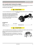
Page 43: ...ole in the direc tion selector mounting bracket preventing movement When in this position the direction selector remains locked in the neutral position To unlock the direction selector 1 Pull the neut...

Page 44: ...eyes Com pletely clean all electrolyte spills that contact the body and eyes with clear water Contact a physi cian immediately Neutralize electrolyte spills with a solution of 2 teaspoons 10 ml sodiu...

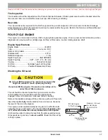
Page 45: ...power 13 hp Spark Plug Type NGK BPR2ES Spark Plug Gap 028 031 70 80 mm Cooling Forced Air Cooled Oil Filter Cartridge Type Full Flow Filter Oil Pump Positive Displacement Pump Checking the Oil Level l...

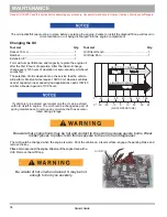
Page 46: ...vehicles require 10W 30 oil whereas vehicles used at capacity or near capacity load applications needs 10W 40 oil after a break in period of 100 hours If vehicle is to be stored over winter months it...

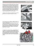
Page 47: ...a around filter Use a filter wrench 3 to remove the filter 4 from the engine and allow the oil to drain The O ring 5 may have remained on engine 6 or filter 7 If the O ring 5 remained on the engine su...

Page 48: ...below the full mark The engine can be operated safely as long as the oil is within the safe operating range as indicated on the dipstick Do not operate the vehicle if the oil level is below the safe...

Page 49: ...the battery case and terminals do not use a water hose without neutralizing any acid deposits first The water hose moves the acid from the top of the battery to another area of the vehicle or storage...

Page 50: ...eaning will assure an ade quate supply of air to the cooling fins Compressed air may be used for routine cooling system maintenance REAR AXLE The rear axle has a lubricant level check plug located on...

Page 51: ...sitioning arrow on cover is pointing upward and all clips are fastened securely If the element is in acceptable condition loose dirt may be removed by tapping the filter lightly Do not use oil on the...

Page 52: ...ehicle and recording the stopping location or stopping distance Several vehicles should be tested when new and the range of stopping locations or distances recorded Over time a subtle loss of performa...

Page 53: ...re not to contact hot objects Raise the rear of the vehicle and support on jack stands before attempting to run the engine Preparing the engine for a prolonged storage period 30 days or more requires...

Page 54: ...ne is still warm change oil 13 Clean body chassis and engine of debris mud chaff or grass CAPACITIES AND REPLACEMENT PARTS CAPACITIES REPLACEMENT PARTS Fuel Tank Early Prod 5 3 gal 20 0 l 87 Octane Mi...

Page 55: ...S Nm BOL TSIZE Grade 2 1 4 5 16 3 8 7 16 1 2 9 16 5 8 3 4 7 8 1 Unlessotherwise noted in text tighten all hardware in accordance with thischart Thischart specifies lubricated torque figures Fastenerst...

Page 56: ...48 MAINTENANCE Read all of SAFETY and this section before attempting any procedure Pay particular attention to Notices Cautions Warnings and Dangers Notes Owner s Guide...

Page 57: ...issing insulation Direction Selector Inspect attachment and mechanism C A C A C A C A Steering Assembly Check for excess play loose or missing hardware Tie Rods Check for excess play bent rods loose o...

Page 58: ...l Joint Check for noise and loose or missing hardware Battery Clean battery and terminals Front Wheel Bearings Check and adjust as required See Repair and Ser vice Manual for procedure C A Rear Axle C...

Page 59: ...n cause some components on the vehicle to fail The manufacturer can not know all possi ble component failures or the methods that failures can occur A vehicle in need of repair does not operate correc...

Page 60: ...0 848 1636 www Jacobsen com Service Parts Manuals and Repair and Service Manuals are available from the manufacturer Copyrighted Material This manual may not be reproduced in whole or in part without...

Reviews: