en-26
5 CONTROLS
0.0 Hours
5.2.Z.1 VISUAL DISPLAY __________________________________________________
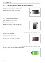
The visual display is activated when the ignition is turned on.
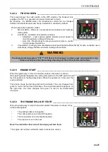
5.2.Z.2
STARTUP SCREEN_________________________________________________
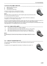
When the ignition key is turned to the start position, this screen is shown.
The hour meter will show total hours of engine operation.
5.2.Z.3
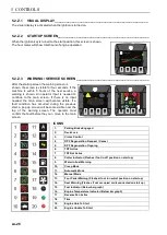
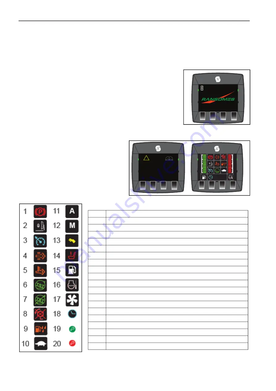
WARNING / SERVICE SCREEN _______________________________________
After the startup screen the warning screen is
shown, the screen is visible for four seconds. If the
machine is within 5 hours of the next service, a
warning is shown. An operator input is needed to
continue to the main screen. If there is no input
needed, the main screen will become visible. If a
fault condition has occurred during the previous
start, a pop up screen will become visible over the
top of the warning screen. The operator must
confirm the fault before they can move to the main
screen.
WARNING
If incorrectly used this machine can cause
severe injury. Those who use and maintain
this machine should be trained in its proper
use, warned of its dangers and should read
the entire operators manual before attempting
to set up, operate, adjust or service the
machine.
TST
™
12 : 34 : 56
0.0 Hours
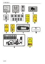
ICONS
1.
Parking Brake Engaged
2.
Deck Lock
3.
Cruise Control
4.
DPF Regeneration Request / Cancel
5.
DPF Regeneration Ongoing
6.
TST Active
7
TST Not Active
8.
Cutter Indicator (Flashes if not in off position on start up)
9.
Water In Fuel Warning
10.
Creep Mode
11.
Automatic Mode
12.
Manual Mode
13.
Foot Pedal Warning (Flashes if not in neutral position on start up)
14.
Seat Warning (Flashes if not occupied or disconnected on start up)
15.
Fuel Indicator (Below bar graph)
16.
Engine Temperature Indicator (Below bar graph)
17.
Reverse Fan Active
18.
Time
19.
Engine Able To Start
20.
Engine Unable To Start
Summary of Contents for ZA5 Series
Page 8: ...en 8 2 INTRODUCTION NOTES...
Page 50: ...en 50 5 CONTROLS NOTES...
Page 51: ...en 51 5 CONTROLS...
Page 63: ...en 62 6 OPERATION 1...
Page 117: ...en 115 QUALITY OF CUT 10 NOTES...
Page 120: ...en 118 11 FUSES RELAYS AND CONTROLLER NOTES...
Page 130: ...en 128 12 SPECIFICATIONS 1...
Page 133: ......


