background image

5/51

4. Symbols

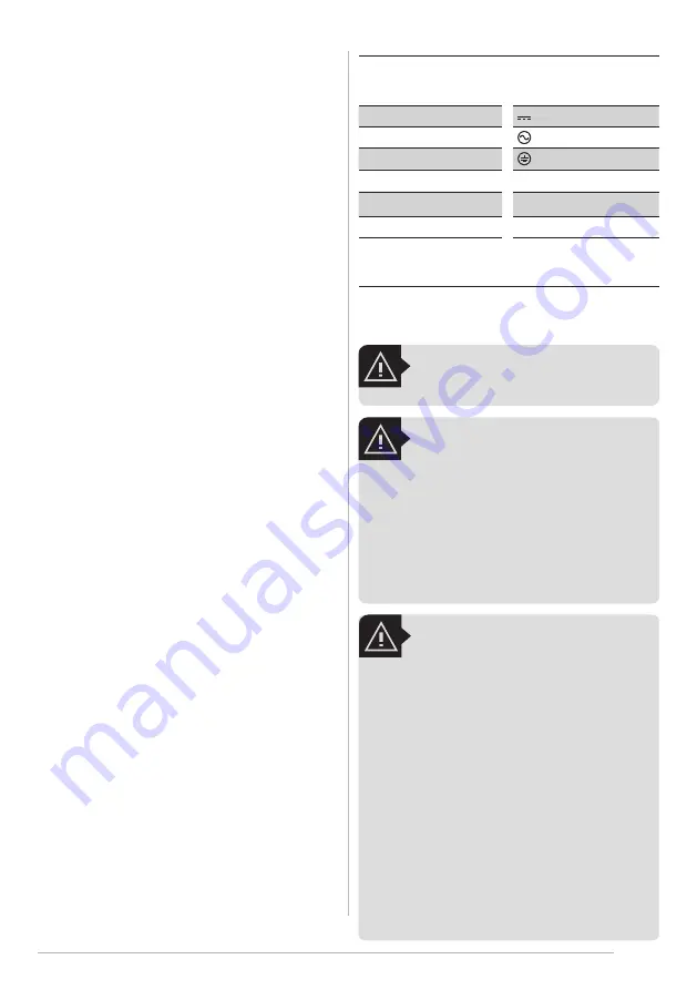
The label on your tool may include the following symbols. The symbols and their 

definitions are as follows:

V

volts

n0

no-load speed

A

amperes

 ou d.c.

direct current

W

watts

 ou a.c

alternating current

Hz

hertz

earthing terminal

lbf/in² (lbf/pol²)

psi

l

litres

min

minutes

kg

kilograms

h

hours

m

meters

3.4. Power tool use and care

a.  Do not force the power tool. Use the correct power tool for your applica-

tion.


The correct power tool will do the job better and safer at the rate for which 

it was designed.

b.  Do not use the power tool if the switch does not turn it on and off.

 Any 

power tool that cannot be controlled with the switch is dangerous and must be 

repaired.

c.  Disconnect the plug from the power source and/or the battery pack from 

the power tool before making any adjustments, changing accessories, or 

storing power tools. 

Such preventive safety measures reduce the risk of starting 

the power tool accidentally.

d.  Store idle power tools out of the reach of children and do not allow per-

sons unfamiliar with the power tool or these instructions to operate the 

power tool.


Power tools are dangerous in the hands of untrained users.

e.  Maintain power tools. Check for misalignment or binding of moving 

parts, breakage of parts and any other condition that may affect the pow-

er tool’s operation. If damaged, have the power tool repaired before use.


Many accidents are caused by poorly maintained power tools.

f.  Keep cutting tools sharp and clean.

 Properly maintained cutting tools with 

sharp cutting edges are less likely to bind and are easier to control.

g.  Use the power tool, accessories and tool bits etc., in accordance with 

these instructions, taking into account the working conditions and the 

work to be performed.


Use of the power tool for operations different from those 

intended could result in a hazardous situation.

3.6. Service

a.  Have your power tool serviced by a qualified repair person using only 

identical replacement parts.

 This will ensure that the safety of the power tool 

is maintained.

3.5. Battery tool use and care

a.  Recharge only with the charger specified by the manufacturer.


A charger 

that is suitable for one type of battery pack may create a risk of fire when used with 

another battery pack. 

b.  Use power tools only with specifically designated battery packs.

 Use of 

any other battery packs may create a risk of injury and fire. 

c.  When battery pack is not in use, keep it away from other metal objects 

like paper clips, coins, keys, nails, screws, or other small metal objects 

that can make a connection from one terminal to another.

 Shorting the 

battery terminals together may cause burns or a fire. 

d.  Under abusive conditions, liquid may be ejected from the battery, avoid 

contact. If contact accidentally occurs, flush with water. If liquid contacts 

eyes, additionally seek medical help.


Liquid ejected from the battery may 

cause irritation or burns.

e.  Do not use a battery pack or appliance that is damaged or modified. 

Damaged or modified batteries may exhibit unpredictable behavior re-

sulting in fire, explosion or risk of injury.

f.  Do not expose a battery pack or appliance to fire or excessive tempera-

ture. Exposure to fire or temperature above 60°C may cause explosion.

WARNING:

Shock hazard.

 Do not allow any liquid to get inside charger.

5. Important Safety Instructions for Battery 

Chargers

SAVE THESE INSTRUCTIONS:


T

his manual contains important safety instructions 

for battery chargers. Before using charger, read all instructions and cautionary 

markings on charger, battery pack, and product using battery pack.

WARNING!

•  DO NOT attempt to charge the battery pack with 

any chargers other than the ones in this manual.


The charger and battery pack are specifically designed 
to work together.

•  These chargers are not intended for any uses other 

than charging designated JACTO lithium recharge-
able batteries.

 Any other uses may result in risk of fire, 

electric shock or electrocution.

•  Do not expose charger to rain or snow.
•  Pull by plug rather than cord when disconnecting 

charger.


This will reduce risk of damage to electric 

plug and cord.

•  Make sure that cord is located so that it will not be 

stepped on, tripped over, or otherwise subjected 
to damage or stress.

•  Do not use an extension cord unless it is absolutely 

necessary.


Use of improper extension cord could result 

in risk of fire, electric shock, or electrocution.

•  An extension cord must have adequate wire size 

(AWG or American Wire Gauge) for safety.

 When 

using more than one extension to make up the total 
length, be sure each individual extension contains at 

CAUTION!

•  Burn hazard.

 To reduce the risk of injury, charge only 

designated JACTO batteries. Other types of batteries 
may burst causing personal injury and damage.

•  Under certain conditions, with the charger plugged 

in to the power supply, the charger can be shorted 
by foreign material. Foreign materials of a conductive 
nature such as, but not limited to, steel wool, aluminum 
foil, or any buildup of metallic particles should be kept 
away from charger contacts. Always unplug the charger 
from the power supply when not charging battery. 
Unplug charger before attempting to clean.

power tool on.


A wrench or a key left attached to a rotating part of the power 

tool may result in personal injury.

e.  Do not overreach. Keep proper footing and balance at all times.

 This en-

ables better control of the power tool in unexpected situations.

f.  Dress properly. Do not wear loose clothing or jewellery. Keep your hair, 

clothing and gloves away from moving parts.

 Loose clothes, jewellery or long 

hair can be caught in moving parts.

g.  If devices are provided for the connection of dust extraction and collec-

tion facilities, ensure these are connected and properly used.

 Use of dust 

collection can reduce dust-related hazards.

Summary of Contents for PJB-16U

Page 1: ...3 Moo 2 Bankhai Banbueng Rd T Nongbua A Bankhai Rayong 21120 Thailand Manual de Instru es Portugu s p gina 15 Manual del Operador Espa ol p gina 26 Manuel du Operateur Fran ais page 37 Code 1251340 Da...

Page 2: ...14 1 Plug type 50 14 2 Pump 51 SUMMARY 1 Introdu o 15 2 Especifica es T cnicas 15 3 Alertas de Seguran a para Ferramenta El trica em Geral 15 3 1 Seguran a da rea de trabalho 15 3 2 Seguran a el trica...

Page 3: ...a garant a 36 13 3 P rdida del derecho de garant a 36 13 4 tems excluidos de la garant a 36 13 5 T rminos generales 36 14 Lista de piezas 48 14 1 Tipos de enchufes 50 14 2 Bomba 51 TABLA DE CONTENIDO...

Page 4: ...e the cord Never use the cord for carrying pulling or un plugging the power tool Keep cord away from heat oil sharp edges or moving parts Damaged or entangled cords increase the risk of electric shock...

Page 5: ...quid contacts eyes additionally seek medical help Liquid ejected from the battery may cause irritation or burns e Do not use a battery pack or appliance that is damaged or modified Damaged or modified...

Page 6: ...harge or use battery in explosive atmospheres such as in the presence of flammable liquids gases or dust Inserting or removing the bat tery from the charger may ignite the dust or fumes If battery con...

Page 7: ...ecommendations and follow manufacturer s disposal instructions Do not pollute the environment Duringthetransportinvehicles thesprayermustbe turned off and secured Always keep the trigger valve shut du...

Page 8: ...t distribution 9 3 Calibration of battery powered knapsack sprayer PROCEDURE 1 USING CALIBRATOR BOTTLE OPTIONAL 2 Hold the lance at the working height and spray to measure the applica tion band width...

Page 9: ...o install the battery in the wrong position 3 Press the battery until a click is heard 9 7 Turning the sprayer on and off To turn on the sprayer turn the potentiometer clockwise and after hearing feel...

Page 10: ...portant care instructions When filling up the tank always use the strainer provided This will reduce the chance of undesirable debris that could damage the pump Do not operate the sprayer without the...

Page 11: ...will help remove chemical residues and extend life of sprayer parts The spray lance can be conveniently stored on the clips on the side of the tank Nozzles and filters must be periodically cleaned or...

Page 12: ...t and output ends of the power supply Replace charger The charger light should turn on or change color when plugged into a power outlet and battery Battery does not hold charge or does not charge Dama...

Page 13: ...e arrow on the pump head with the flow of hoses inlet suction and outlet pressure Position and assemble hoses or valves correctly as specified in the service manual Spraying should occur normally Lanc...

Page 14: ...he factory 13 3 This warranty shall be null void in case of Misuse of the equipment against specifications in this manual overwork or accidents Use the equipment to spray products not intended for pla...

Page 15: ...al de Instru es Dr Luiz Miranda 1650 17580 000 Pompeia SP Brasil Telefones 0800 151 811 ou 0800 772 2100 E mail atendimento jacto com br Home page www jacto com Fabricado por INTERMAN Corporation Ltd...

Page 16: ...A utiliza o de ferramenta el trica para opera es diferentes das quais o mesmo se destina podem resultar em uma situa o perigosa 3 5 Uso e cuidado da bateria a Recarregue somente com o carregador espec...

Page 17: ...nte carregada Antes de utilizar a bateria e o carregador leia as seguintes instru esdeseguran a Depois sigaosprocedimentosde carregamento descritos 6 Instru es de Seguran a Importantes para a Bateria...

Page 18: ...nda esdofabricante Alta press o presente na lan a de pulveriza o e dentro da base do pulverizador Desligue o pul verizador completamente e libere a press o antes de tentar consertar ou substituir pe a...

Page 19: ...e plano uniforme Jacto JEF 8002 com boa faixa de aplica o devido ao ngulo de abertura de 80 gotas finas para tima cobertura e vaz o de 0 8 L min a 45 psi ideal para aplica es perime trais e em rea tot...

Page 20: ...a possui formato anat mico proporcionando maior como didade ao operador O posicionamento correto da m quina no corpo do operador pode ser obtido com um simples ajuste da cinta 1 Monte a cinta no tanqu...

Page 21: ...cer piscando at que o usu rio desligue o pulverizador 9 9 N veis de press o Para regular o n vel de press o Posicione a lan a de pulveriza o para uma dire o segura e aperte o gatilho para come ar a pu...

Page 22: ...evapora o das got culas As condi es ideais para pulveriza o s o Umidade relativa m nima de 50 Velocidade do vento 3 10 Km h Temperatura abaixo de 30 C Esses limites devem ser considerados de acordo c...

Page 23: ...ntinuidade posicionando as hastes do mult metro nas extremidades de entrada e sa da da fonte Trocar carregador A luz do carregador deve acen der ou mudar de cor quando conectado tomada e bateria Bater...

Page 24: ...indicativa no cabe ote da bomba com o fluxo das mangueiras entrada suc o e sa da press o Posicionar e montar as manguei ras ou v lvulas da forma correta conforme especificado no manual de servi o Pulv...

Page 25: ...13 3 Perda do direito de garantia Utiliza o do equipamento em desacordo com as recomenda es t cnicas do manual de instru es sobrecargas de trabalho ou acidentes Utiliza o do equipamento para pulveriz...

Page 26: ...ias puede resultar en descargas el ctricas incendio o lesiones graves CUIDADO Indica una situaci n potencialmente peligrosa que si no se evita pue de resultar en lesiones leves o moderadas NOTA El uso...

Page 27: ...rica con prudencia No la utilice si estuviera cansado o bajo efecto de drogas alcohol o medicamentos Unmomentodedescuidomientrasope ra una herramienta el ctrica puede resultar en lesiones personales g...

Page 28: ...nchufe del cargador al conector de la bater a 4 La luz de carga permanecer roja naranja durante la carga 5 Cuando la bater a est completamente cargada la luz de carga cambiar para el color verde 6 As...

Page 29: ...pl sticos y de vidrio cada envase debe lavarse tres veces para garantizar que los residuos sean eliminados completamente Este manual describe c mo hacer el triple lavado de manera correcta segura y ef...

Page 30: ...EF 8002 con un buen rango de aplicaci n debido al ngulo de apertura de 80 gotas finas para una cobertura ptima y un caudal de 0 8 L min a 45 psi ideal para aplicaciones perimetrales y en rea total Boq...

Page 31: ...El tanque del equipo tiene forma anat mica que le proporciona mayor confort al operador El posicionamiento correcto del equipo en el cuerpo del operador puede obtenerse simplemente ajustando la corre...

Page 32: ...rpadeando hasta que el usuario apague el pulverizador Cuando la bater a se descargue completamente durante la pulverizaci n la bom ba se apagar autom ticamente y el LED seguir parpadeando Apague el pu...

Page 33: ...aci n de las gotas Las condiciones ideales para pulverizaci n son Humedad relativa m nima de un 50 Velocidad del viento 3 10 km h Temperatura por debajo de 30 C Esosl mitesdebenconsiderarseseg nlatecn...

Page 34: ...Programar el mult metro para medici n de continui dad y verificar si hay continuidad posicionando las puntas del mult metro en las extremidades de entrada y salida de la fuente de alimentaci n Cambia...

Page 35: ...omba y el flujo de las mangueras entrada succi n y salida presi n Posicionar y montar correctamen te las mangueras o v lvulas de acuerdo con lo especificado en el manual de servicios La pulverizaci n...

Page 36: ...de an lisis con clusivo en la f brica 13 3 P rdida del derecho de garant a Uso del equipo en desacuerdo con las recomendaciones t cnicas del ma nual de instrucciones sobrecargas de trabajo o accidente...

Page 37: ...entra ner la mort ou des blessures graves ATTENTION Indique une situation potentiellement dangereuse qui si elle n est pas vit e peut entra ner des blessures mineures ou mod r es REMARQUE Utilis sans...

Page 38: ...ante de l outil peut entra ner des blessures e Ne surestimez pas Conserver son quilibre en tout temps Cela permet un meilleur contr le de l outil lectrique dans des situations impr vues f Portez des v...

Page 39: ...nt charg e la lumi re de charge va changer sa couleur verte 6 D s que la batterie est compl tement charg e d branchez la batterie du chargeur 7 D branchez le cordon du chargeur de la prise Rechargebat...

Page 40: ...courts circuits Pour le transport des piles individuelles s assurer que les bornes de la batterie sontprot g esetbienisol es partirdemat riauxpou vant entrer en contact et de provoquer un court circu...

Page 41: ...3 Monter le bouchon du r servoir et serr il suffi t d viter les fuites pendant l agitation 4 Agiter le r cipient fermement par tous les moyens horizontales et verti cales pendantenviron30secondespour...

Page 42: ...ion du liquide et remplissage du r servoir 1 Pour diluer et pr m langer le produit placer 5 litres d eau dans un r ci pient s par 2 M langer jusqu l obtention d un liquide homog ne et verser dans le r...

Page 43: ...te de connecter une batterie diff rente de celle d origine La LED continuera clignoter jusqu ce que l utilisateur arr te le pulv risateur Lorsque la batterie est compl tement d charg e pendant la pulv...

Page 44: ...mmager la pompe Ne pas faire fonctionner le pulv risateur sans le filtre pompe d aspiration Cela peut gravement endommager la pompe P riodiquement nettoyer ou rem placer ce filtre comme suit 1 Videz l...

Page 45: ...ra medici n de continui dad y verificar si hay continuidad posicionando las puntas del mult metro en las extremidades de entrada y salida de la fuente de alimentaci n Cambiar el cargador La luz del ca...

Page 46: ...a y el flujo de las mangueras entrada succi n y salida presi n Posicionar y montar correcta mente las mangueras o v lvulas de acuerdo con lo especificado en el manual de servicios La pulverizaci n deb...

Page 47: ...lyse conclusive la fa brique 13 3 Pertedudroitdegarantie Emploi du pulv risateur en d saccord avec les recommendations techniques du MA NUELD INSTRUCTIONS ouencasd abus desurchargesdetravailoud accide...

Page 48: ...48 51 14 Parts list lista de pe as lista de piezas pi ces d tach es 1 2 3 4 5 6 7 8 39 9 10 11 12 13 14 15 16 17 18 19 20 21 14 22 23 24 25 26 27 28 29 30 31 32 33 34 35 36 37 38...

Page 49: ...METRO PANEL COMPLETO CON POTENCIOMETRO PANNEAU COMPLET AVEC POTENTIOMETRE 1 14 1220622 FLANGE HEAD SCREW PHILLIPS SLOT 5 X 12 MM PARAF CAB FLANG PH 5 X 12 MM TORNILLO PH 5 X 12 MM VIS DE T TE FLANGE...

Page 50: ...COMPL TE LP 601U 1 32 1220969 SCREW CAP 11 16 PORCA C NICA 11 16 TUERCA CONICA 11 16 BOULON CONIQUE 11 16 2 33 635276 JOINT AND CONE PACKING JUN O E JUNTA C NICA UNI N CON JUNTA C NICA JOINT AND CONE...

Page 51: ...DA BOMBA U DIAFRAGMA DE LA BOMBA U DIAPHRAGME DE POMPE U 2 4 1265947 HEAD SEAL VEDA O DO CABE OTE EMPAQUETADURA DEL CABEZAL JOINT DE TETE 2 5 1265958 PRESSURE SWITCH MEMBRANE MEMBRANA DO PRESSOSTATO...

Reviews: