Page 46
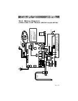
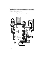
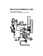
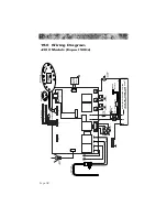
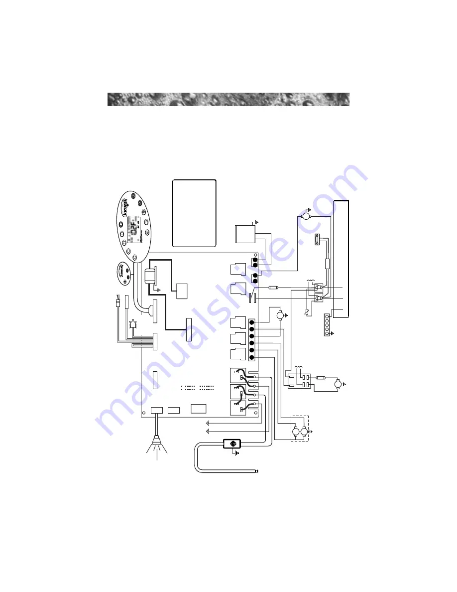
17.0 Wiring Diagram
J-380 Models (USA/Canada 60Hz)
SENSORS
Power Input: 240 V
AC, 60A
/ 50A
/ 40A
1 PHASE, 60Hz; USE MIN. 6
A
WG (10 mm
2
)
COPPER CONDUCT
ORS ONL
Y
J4
J8
J2
K8
K6
K5
K4
K1
K2
K3
K7
J1
Z1
J6
J7
J3
OPTIONS
FLOW SWITCH
HI - LIMIT
/ FREEZE SENSOR
TRANSFORMER
T1
RED
Red
Wht
Wht
Wht
Blk
Blk
Red
Blk
BLK
Blk
20A, 250V
MDA20
F2
PUMP
3
PUMP
1
T92
Relay
HI
Wht
Wht
Blk
Blk
PUMP
2
HI
HI
LO
TB3
TB2
TB6
TB1
TB1
GRN
1
3
5
6
8
10
1
2
1
2
JP20
JP19
JP9
1
1 3 5 7 9
1 3 5 7 9
11 13
TEMPERA
TURE
SENSOR
To
Heater &
Pump 2 Relay
From
TB1
SP
A
LIGHT
TB5
From TB1
30A,
250V
SC-30
F1
UV or CD
Ozonator
(Optional)
INTERLOCK
JUMPER
Circulation
Pump
STEREO
(Optional)
This device complies with part 15 of
the FCC rules. Operation is subject to
the following two conditions:
1.
This device may not cause harmful
interference.
2.
This device must accept any
interference received including
interference that may cause
undesired operation.
Power Supply
Remote Panel
Main Panel
HEA
TER
5.5 kW
Select
Cycle
Mode
Display
y
y
Change
Filter

