Section 2b
– INSTALLATION
Cell and Manifold Installation
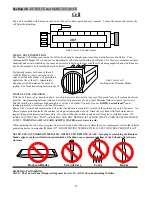
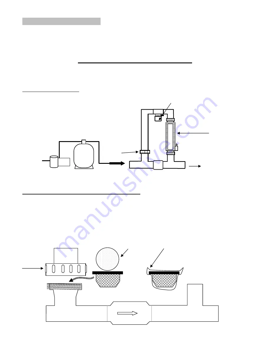
Your Commander III Model JC7 System is adaptable for use with the 7 blade (JC7) cell. The manifold must be located as the
last accessory in the
POOL RETURN LINE
only. For special plumbing configurations, please contact your representative for
assistance in locating the manifold.
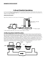
Standard Manifold Assembly:
Bypass flow rate should be set at 94.5 L/min. (25 US Gallons/min.
)
.
Tri sensor
6
Commander III = JC7 Cell
union
flow in flow out to pool
For other plumbing configurations, please contact your representative for assistance.
Verification of Flow Switch Protection:
It is important to
ANNUALLY
inspect and verify the safe and proper operation of the Tri-sensor’s Flow Switch protection
device. We recommend following this procedure to verify that the flow switch is working as designed, which is to halt power
from being sent to the cell in the presence of insufficient flow. A defective Flow Switch could cause serious personal and/or
equipment damage. Using either a GOLF BALL or small plastic wrap (saran wrap, food wrap or zip lock bag), block off flow
to the upper portion of the manifold by placing the golf ball in the strainer screen union or by wrapping the strainer screen with
the plastic wrap and placing it back in the union and tightening. Operating the system on with this blockage should detect a
FLOW obstruction, indicated on the digital display and activating a red flashing CHECK SYSTEM light. Once this protection
feature has been verified, remove the plastic wrap or golf ball, replace the strainer screen and resume operation. Turn the
output dial to OFF and contact the factory if the flow switch protection is not working properly.
Golf
Ball
Plastic
Wrap
C
LEAN UNION
SCREEN
REGULARLY
OR
union


