background image

Page 36

J-400 Series

L

K

4

4

3

3

5

3

3

1

1

2

2

2

4

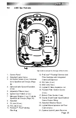
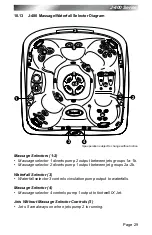
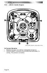
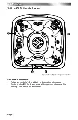
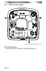
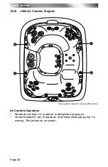
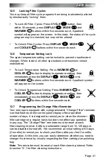
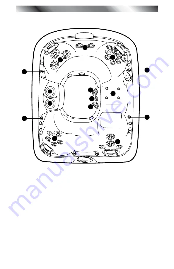
air Controls Operation

• 

Rotate air controls 1-4 to add air to designated jet groups.

• 

Center footwell IX Jet (5) draws air at all times when jets pump 1 is 

running. This jet has no air control.

10.20  J-460 air Controls Diagram

Spa operation subject to change without notice.

Summary of Contents for J - 400 SERIES J - 465

Page 1: ...Owner s manual J 4 0 0 S e r i e s J 460 J 465 J 470 J 480 2530 442U Rev A ...

Page 2: ...de Remote Style A includes a light MODE Button Remote Style B replaces this button with an AIR button that is illustrated by three rows of circles Both buttons select the light system color mode Refer to section 9 6 in the supplied Owner s Manual for light system operation details 2 Remote Style A has a Zone 2 Up and Down Button Remote Style B replaces these buttons with a single AMP SOURCE Button...

Page 3: ...7 6 Free chlorine 3 0 4 0 ppm Free bromine 2 0 4 0 ppm Total Alkalinity 100 120 ppm Calcium Hardness 150 250 ppm TO DECREASE RISK OF INFECTION OR DISEASE Always maintain your spa filter as outlined below to ensure healthy spa water Refer to pages 49 50 sec 14 0 for additional information Required Filter Maintenance Your new spa is equipped with an advanced water filtration system that provides uns...

Page 4: ...5 J 465 Spa Features 24 9 6 J 460 Spa Features 25 10 0 Operating Instructions 26 10 1 View Button 26 10 2 Activate Jets Pump 1 26 10 3 Activate Jets Pump 2 26 10 4 Selecting the Desired Massage Action 26 10 5 Light On Off Button 26 10 6 Light Mode Button 27 10 7 Adjusting Individual Jet Flow 27 10 8 Adjusting PowerPro MX2 Jets 27 10 9 Adjusting RX Jets 27 10 10 WaterColour Waterfall Control 28 10 ...

Page 5: ...nce 49 14 1 pH Control 49 14 2 Sanitizing 49 14 3 Other Additives 50 14 4 Ozone Water Maintenance System 50 15 0 Troubleshooting Display Messages 51 16 0 Troubleshooting Procedures 53 17 0 North American 60 Hz J 460 J 465 J 470 J 480 Wiring Diagram 55 18 0 Export 50 Hz J 460 J 465 J 470 J 480 Wiring Diagram 56 19 0 Typical Spa Wiring Diagrams A B North American 60Hz Models Only 57 20 0 Optional Ja...

Page 6: ...e limits are designed to provide reasonable protection against harmful interference in a residential installation This equipment generates uses and can radiate radio frequency energy and if not installed and used in accordance with the instructions may cause harmful interference to radio communications However there is no guarantee that interference will not occur in a particular installation If t...

Page 7: ...ponents to avoid entrapment that could lead to drowning or severe injury Never use the spa unless all suction guards filter filter lid or skimmer assembly are installed to prevent body and or hair entrapment Never operate or use the spa if the filter filter lid or skimmer assembly are broken or any part of the skimmer assembly is missing Please contact your dealer or nearest service center for ser...

Page 8: ...uitable ground fault circuit interrupter GFCI as required by NEC Article 680 42 4 WARNING Risk of Severe Injury or Death Extreme caution must be exercised to prevent diving or jumping into the spa or slipping and falling which could result in unconsciousness drowning or serious injury Remember that wet surfaces can be very slippery Never stand walk or sit on the top railing of the spa 5 WARNING Ri...

Page 9: ...ing spa use may lead to unconsciousness with the possibility of drowning 7 WARNING Risk of Severe Injury or Death Prolonged immersion in a spa may be injurious to your health Observe a reasonable time limit when using the spa Exposures at higher temperatures can cause high body temperature over heating Symptoms may include dizziness nausea fainting drowsiness and reduced awareness These effects co...

Page 10: ...one locality to another Hot Tub Safety Literature To ensure you have a safe and enjoyable hot tub experience learn all you can about hot tub safety and emergency procedures Especially useful are the brochures listed below Children Aren t Waterproof Pool and Spa Emergency Procedures For Infants and Children Layers of Protection The Sensible Way to Enjoy Your Spa or Hot Tub The Association of Pool a...

Page 11: ...s has been reported in persons who when submerge themselves underwater allowing hair to come close and or within the reach of the suction fittings suction covers or skimmer assembly Keep hair away from suction fittings suction covers filter filter lid or skimmer assembly Children are at risk for hair entrapment if swimming under water Never allow children to play or get near the suction fittings s...

Page 12: ... or skimmer assembly Never allow children to play or get near the suction fittings suction covers filter filter lid or skimmer assembly 3 2 Hyperthermia Prolonged immersion in hot water may induce hyperthermia over heating The use of alcohol or drugs can greatly increase the risk of fatal hyperthermia in spas A description of the causes symptoms and effects of hyperthermia are as follows Hyperther...

Page 13: ...ulated or bare copper conductor not smaller than No 6 AWG 10 mm 4 All field installed metal components such as rails ladders drains or other similar hardware within 10 feet 3m of the spa shall be bonded to the equipment grounding buss with copper conductors not smaller than No 6 AWG 10 mm 5 SAVE THESE INSTRUCTIONS 4 0 Choosing a Location IMPORTANT Because of the combined weight of the spa water an...

Page 14: ...ns needed to vent moist or heated air and air associated with chemical odors outdoors When the spa is in use considerable amounts of moisture will escape potentially causing mold and mildew This can cause health risk Over time this can damage certain surfaces surroundings and equipment 4 1 Outdoor Location In selecting the ideal outdoor location for your spa we suggest that you take into considera...

Page 15: ...esist water and moisture Proper Ventilation Proper ventilation should be discussed with an Engineer or authority competent enough to understand the necessary provisions needed to vent moist or heated air and air associated with chemical odors outdoors When the spa is in use considerable amounts of moisture will escape potentially causing mold and mildew over time which can damage certain surfaces ...

Page 16: ...ur local building department to ensure installation conforms to local building codes 6 0 Electrical Installation Instructions 240V Service IMPORTANT NOTICE The electrical wiring of this spa must meet the requirements of the National Electrical Code USA NEC and any applicable state or local codes The electrical circuit must be installed by a qualified electrician and approved by a local building el...

Page 17: ...electrical circuit supplied for the spa must include a suitable ground fault circuit interrupter GFCI as required by NEC Article 680 42 USA 6 To gain access to the spa s power terminal block remove the four screws securing the center cabinet panel on the side of the spa under the controls Then remove the four control box door screws and door Figure A 7 Select the power supply entrance you want to ...

Page 18: ...Control Box 2 Power Supply Entrance s 3 Jet Pump 1 4 Heater 5 Spa Drain Valve 6 Pump Drain Plugs s 7 Jets Pump 2 8 Filter Circulation Pump 9 Optional CD Ozonator Purchase Separately 10 Factory Installed Ozone Injector 11 Control Panel Figure B Control Box TB1 3 2 1 1 Terminal Block 2 Bonding Lug 3 Grounding Terminal ...

Page 19: ...ow All North American 60Hz Models 240VAC 50A All Export 50Hz Models 230VAC 30A If you prefer your qualified technician can perform a minor circuit board modification that allows the hot tub to operate on a different electrical service see table footnotes below North American J 460 J 465 J 470 J 480 Models 60Hz Voltage 240 VAC 240 VAC 240 VAC Max Current Draw 23A 36A 45A Frequency 60 Hz 60 Hz 60 Hz...

Page 20: ...he factory you may want to treat it with a specially formulated spa cleaner Consult your authorized Jacuzzi dealer for additional information prior to filling spa Remove both ProClear Plus skimmer and polishing filter lids and filters as illustrated in section 13 1 page 43 2 Fill Spa Place the end of your garden hose into empty skimming filter bucket filter bucket on your left as you stand next to...

Page 21: ...s Pumps Turn on all jets s pumps when adding chemicals in step 5 5 Add Start Up Chemicals Add the spa water chemicals as recommended by your authorized Jacuzzi spa dealer See section titled Water Quality Maintenance page 49 for general guidance WARNING Risk of poisoning or death Never leave chemicals opened and accessible to anyone Use chemicals according to the vendors instructions Always store c...

Page 22: ...ts pumps on Setting the thermostat at maximum will not accelerate the heating process This will only result in a higher ultimate temperature The heater operates until the water reaches 1 degree above the programmed set temperature then turns off The heater will reactivate after the water cools to approximately 1 degree below the set temperature 8 Place Cover On Spa Keeping the insulating cover in ...

Page 23: ...emical attack If spa is indoors open doors and windows for proper ventilation Turn on all spa jet pumps for one hour open all air controls and place all massage selector knob s in their center combo position as shown Note You will need to activate the jet pumps every 20 minutes since these functions have an automatic 20 minute time out that turns them off WARNING risk of PERSONAL INJURY To decreas...

Page 24: ...ERSONAL INJURY To decrease the risk of injury drowning or entrapment never leave your hot tub unattended for any reason while the cover is open and accessible especially to small children and animals Precautions should be taken to minimize your exposure to chemical vapors that could cause lung brain or skin damage 7 Establish a sanitizer reading between 3 0 4 0 ppm chlorine or 2 0 4 0 ppm bromine ...

Page 25: ...e main 4 digit LCD display F Warmer and Cooler Buttons Press these to display increase or decrease the temperature They also display other programmable features G Light On Off Button Turns waterfall footwell and logo lights on in unison Press once for high intensity press a second time for medium intensity press a third time for low intensity press a fourth time to turn off The displayed color is ...

Page 26: ...ates programmed filter cycle is running Filter Cycle Start Time Indicates filter cycle start time programming is accessed Filter Cycle Duration Indicates filter cycle duration programming is accessed Set Temperature Indicates the current set temperature is displayed Set Time Indicates current time is displayed Filter Annunicator Indicates filter cleaning and or replacement Jets 1 Indicates jets pu...

Page 27: ...oClear Plus Polishing Filter 10 Bag and Filter ProClear Floating Skimmer And 11 Filter Cartridge with Integrated Chemical Dispenser NX Jets 2 ea And MX2 Jets 3 12 ea FX2 Jets 2 ea 13 NX Jets 2 ea And RX Jets 10 14 ea Lounge Jets 15 FX Back Jets 6 ea SX2 Jet for Wrists And Calves 6 ea Lighted Seat Logo 16 Footwell Filter Suction Covers 3 17 ea Bottom Filter Suction Cover 18 Waterfall Filtration Ret...

Page 28: ...Chemical Dispenser NX Jets 2 ea And MX2 Jets 3 12 ea FX2 Jets 2 ea 13 NX Jets 2 ea And RX Jets 10 14 ea FX2 Jet 15 Lighted Seat Logo 16 Footwell Filter Suction Covers 3 17 ea Bottom Filter Suction Cover 18 Waterfall Filtration Return 19 FX Calf Jets 2 ea 20 FX Footwell Jets 4 ea 21 Lighted IX Mass Aspiration Jet 22 Gravity Drain Heater Input Optional 23 Ozone Return Fitting Lighted Mass Aspiration...

Page 29: ...1 Filter Cartridge with Integrated Chemical Dispenser Footwell Filter Suction Covers 3 12 ea Bottom Filter Suction Cover 13 NX Jets 2 ea 14 FX2 Jets 7 ea 15 SX2 16 Jets 4 ea RX Jets 4 ea 17 MX Jets 5 ea 18 Lighted IX Mass Aspiration Jet 19 Gravity Drain Heater Input Optional 20 Ozone Return Fitting Waterfall Filtration Return 21 Lighted Mass Aspiration Jet Flow 22 Control Valve Optional Audio Syst...

Page 30: ... ProClear Floating Skimmer And 12 Filter Cartridge with Integrated Chemical Dispenser SX2 13 Jets 4 ea MX2 Jets 5 ea 14 Lighted IX Mass Aspiration Jet 15 Footwell Filter Suction Covers 16 3 ea Bottom Filter Suction Cover 17 Gravity Drain Heater Input Optional 18 Ozone Return Fitting Waterfall Filtration Return 19 Lighted Mass Aspiration Jet Flow 20 Control Valve Optional Audio System Receiver 21 1...

Page 31: ...inutes If at this time you desire more jet operation you may simply turn the pump s back on 10 4 Selecting the Desired Massage Action Your Jacuzzi spa is equipped to allow you to customize the massage action you desire Each model incorporates a massage selector that allow you to customize the massage and performance by diverting water between various jet systems Simply turn massage selector to pos...

Page 32: ... hundreds of colors in 5 second intervals 10 7 Adjusting Individual Jet Flow The water flow to certain jets in your spa can be increased or decreased by rotating the outside jet face Note Always keep at least 6 adjustable jets open at all times 10 8 Adjusting PowerPro MX2 Jets Tilt PowerPro MX2 Jet nozzle to angle of choice as desired Rotate nozzle clockwise to reduce flow volume from jet or rotat...

Page 33: ... air control clockwise to open or rotate counterclockwise to close To minimize heat loss all air controls should be closed when the spa is not in use 10 12 Optional J 1000 Jacuzzi Audio System Jacuzzi models equipped with the optional audio system offer enhanced hot tub enjoyment by offering an integrated state of the art audio system These models include an integrated AM FM CD MP3 iPod USB and NA...

Page 34: ...1 output between jet groups 2a 2b Waterfall Selector 3 Waterfall selector 3 controls circulation pump output to waterfalls Massage Selector 4 Massage selector 4 controls pump 1 output to footwell IX Jet Jets Without Massage Selector Controls 5 Jets 5 are always on when jets pump 2 is running 10 13 J 480 Massage Waterfall Selector Diagram Spa operation subject to change without notice ...

Page 35: ...Controls Operation Rotate air controls 1 4 to add air to designated jet groups Center footwell IX Jet draws air at all times when jets pump 1 is running This jet has no air control 10 14 J 480 Air Controls Diagram Spa operation subject to change without notice ...

Page 36: ...utput between jet groups 2a 2b Waterfall Selector 3 Waterfall selector 3 controls circulation pump output to waterfalls Massage Selector 4 Massage selector 4 controls pump 1 output to footwell IX Jet Jets Without Massage Selector Controls 5 Jets 5 are always on when jets pump 2 is running 10 15 J 470 Massage Waterfall Selector Diagram Spa operation subject to change without notice ...

Page 37: ...rols Operation Rotate air controls 1 4 to add air to designated jet groups Center footwell IX Jet draws air at all times when jets pump 1 is running This jet has no air control 10 16 J 470 Air Controls Diagram Spa operation subject to change without notice ...

Page 38: ...ge Selector 2 Massage selector 2 controls pump 1 output to footwell IX Jet Waterfall Selector 3 Waterfall selector 3 controls circulation pump output to waterfall Jets Without Massage Selector Controls 4 Jets 4 are always on when jets pump 2 is running 10 17 J 465 Massage Waterfall Selector Diagram Spa operation subject to change without notice ...

Page 39: ... 34 J 400 Series 1 1 2 2 2 2 2 3 3 3 1 3 2 Air Controls Operation Rotate air controls 1 3 to add air to designated jet groups 10 18 J 465 Air Controls Diagram Spa operation subject to change without notice ...

Page 40: ...ge Selector 2 Massage selector 2 controls pump 1 output to footwell IX Jet Waterfall Selector 3 Waterfall selector 3 controls circulation pump output to waterfall Jets Without Massage Selector Controls 4 Jets 4 are always on when jets pump 2 is running 10 19 J 460 Massage Waterfall Selector Diagram Spa operation subject to change without notice ...

Page 41: ...trols Operation Rotate air controls 1 4 to add air to designated jet groups Center footwell IX Jet 5 draws air at all times when jets pump 1 is running This jet has no air control 10 20 J 460 Air Controls Diagram Spa operation subject to change without notice ...

Page 42: ...ers in warm climates where heat up times are minimized due to higher ambient temperatures In this mode the water temperature is regulated by the set temperature only when a programmed filter cycle is running unless in summer logic page 39 11 3 Selecting Standard or Economy Mode Press the MODE button to select either Standard or Economy mode The control panel s indicator on the right side of the LC...

Page 43: ...am the duration time in 1 hour increments Press DISPLAY button to save changes and recall the main water temperature display Note If no button is pressed within 30 seconds all changes are recorded and the screen automatically returns to the standard water temperature display When the standard mode is selected sec 11 1 page 37 the filter circulation pump automatically turns on for a heat call regar...

Page 44: ...ramming mode The LCD screen will display the following in the upper right corner 1 This means the system is ready to accept your changes to the start time for cycle number one Simultaneously the large four digit display in the center of the screen displays the currently programmed start time for that cycle At this point you have four options You may 1 Press WARMER or COOLER button to adjust the st...

Page 45: ... followed by AM or PM The hour will advance or decrease each time WARMER or COOLER button is pressed within five seconds Then press DISPLAY button again to display the minutes Adjust the minutes as necessary by pressing WARMER or COOLER button After 5 seconds the display will return to normal and save your settings 12 4 Main Control Panel Lock To help prevent unauthorized use of your spa the Sentr...

Page 46: ... the screen To Unlock Temperature Setting Press WARMER or COOLER button to display temperature setting then immediately press the DISPLAY MODE and COOLER buttons within five seconds each 12 7 Programming the Change Filter Reminder Your new spa is equipped with a programmable Change Filter reminder icon that flashes on the control panel display after a specified number of days It is designed to rem...

Page 47: ...ilter cleaning interval 3 Press WARMER or COOLER button to change duration setting as follows 0 10 20 30 40 50 60 70 80 90 100 110 120 OFF Note Selecting 0 in step 3 forces the change filter reminder icon to remain on indefinitely 4 Press DISPLAY button once to save changes and return to the standard water temperature display Note If no button is pressed within 30 seconds all changes are recorded ...

Page 48: ...itting or suction cover with one rated less than the flow rate marked on the original suction fitting Using improper suction fittings or suction covers can create a body or hair suction entrapment hazard that may lead to drowning or severe injury Owners must alert all spa users to the potential risk of Hair Limb Body Evisceration disembowelment and Mechanical Entrapment page 6 13 1 Cleaning the Fi...

Page 49: ... A or filter bag cover B 2 Remove the polishing bag lid B by rotating it counterclockwise approximately 5 degrees until you feel it unlatch 3 Remove the polishing bag by reaching into the filter bucket and gently pulling upward on the blue filter ring empty filter bag weekly or install a new bag every three months Located below the bag is a small Proclear filter Remove the filter by rotating it co...

Page 50: ...ven though the key water balance measurements are all within the proper parameters CAUTION READ THIS BEFORE DRAINING To reduce risk of damage to the spas components turn off power to the spa at the circuit breaker before draining it Do not turn the power back on until your spa has been refilled CAUTION There are certain precautions to keep in mind when draining your spa If it is extremely cold and...

Page 51: ...is not necessary to remove the headrests for cleaning To remove headrests for long term storage or replacement grasp both ends of each headrest and gently pull inward towards the center of the spa To reinstall over mounting strip and press down until headrest mounting bracket emits a click sound Then adjust headrest height by simply moving up or down as desired 13 5 Maintaining the Synthetic Cabin...

Page 52: ...winterization of your spa contact your authorized Jacuzzi dealer In emergency situations damage can be minimized by taking the following steps CAUTION TURN OFF POWER TO SPA 1 Follow the directions on page 45 for draining the spa 2 As the water level drops below the seats use whatever means necessary to get the water out of the recessed seating areas and into the footwell 3 When the water level cea...

Page 53: ...ur spa after it has sat empty for a time in freezing temperatures be aware that the water remaining in certain sections of the piping may still be frozen This situation will block water flow preventing the spa from operating properly and possibly damaging the equipment We recommend you consult your dealer for guidance before attempting to restart your spa under these conditions ...

Page 54: ...vices are located This area is not intended for storage of any kind 14 1 pH Control pH is a measure of relative acidity or alkalinity of water and is measured on a scale of 0 to 14 The midpoint of 7 is said to be neutral above which is alkaline and below which is acidic In spa water it is very important to maintain a slightly alkaline condition of 7 4 to 7 6 Problems become proportionately severe ...

Page 55: ...ash and void the manufacturer warranty for your spa 14 3 Other Additives Many other additives are available for your spa Some are necessary to compensate for out of balance water some aid in cosmetic water treatment and others simply alter the feel or smell of the water Your Authorized Jacuzzi dealer can advise you on the use of these additives 14 4 Ozone Water Maintenance System This system is op...

Page 56: ...et point jets pump 1 and heater will automatically activate to provide freeze protection The spa will stay in this mode until the water temperature reaches 15 degrees below the set temperature No corrective action is necessary FLOW SWITCH Heater is deactivated The filter circulation may also be deactivated Proper flow of water is inhibited or a flow switch has malfunctioned Check for proper water ...

Page 57: ...G spa is deactivated WARNING Risk of Hyperthermia over heating Causing Severe Injury burns or welts A problem has been detected which could cause damage to the spa or its components Contact your dealer or service organization OPEN SENSOR heater disabled OR SHORTED SENSOR spa is deactivated The high limit temperature sensor is non functional This must be repaired only by a dealer or qualified servi...

Page 58: ...T OPERATE AND ICON DOES Depress JETS button 1 If no sound is detected or if a buzzing sound and icon does is detected turn off power to the spa and contact your dealer or service center 2 If motor operates but no water flows to jets A Pump may not be properly primed See instructions below B Contact dealer or authorized service center Pump Priming Instructions 1 Turn off power to the spa 2 Remove t...

Page 59: ...ed service center FILTER CIRCULATION PUMP OFF 1 Verify filter circulation pump is programmed to run 24 hours a day page 38 2 Filter circulation pump cycle canceled by power interruption Wait 24 hours for hot tub to reset 3 Hot tub water is warmer than 95 F 35 C and two degrees warmer than the set temperature The Summer Logic safety feature has activated See note on page 39 for details Jacuzzi buil...

Page 60: ...ays TB1 TB3 TB1 TB2 TB6 TB4 STEREO Optional Main Power On Off Shutoff Switch GRN External Service Panel Box Disconnect Means Must Be Located No Closer Than 5FT 1 52 Meters From Edge And Within Sight of Spa 240VAC 60Hz 23A 38A 45A 1 Phase Use Copper Conductors Only Use Min 8AWG 75 C Wire Size Wire Size Must Be Appropriate Per NEC And Or Local Codes 1 3 5 7 9 1 3 5 7 9 11 13 JP19 JP20 JP9 1 3 5 7 9 ...

Page 61: ...TB3 TB1 TB2 TB6 TB4 STEREO Optional Main Power On Off Shutoff Switch GRN External Service Panel Box Disconnect Means Must Be Located No Closer Than 5FT 1 52 Meters From Edge And Within Sight of Spa 240VAC 60Hz 23A 38A 45A 1 Phase Use Copper Conductors Only Use Min 8AWG 75 C Wire Size Wire Size Must Be Appropriate Per NEC And Or Local Codes 1 3 5 7 9 1 3 5 7 9 11 13 JP19 JP20 JP9 1 3 5 7 9 1 3 5 7 ...

Page 62: ... L1 Green GFCI Sub Panel Main Panel 2 Pole GFCI Breaker Ground Bonding Lug No Load Neutral Wire Main Panel with Secondary GFCI Shut Off Box Using a 2 Pole GFCI Breaker with 2 Wire Grounded Connection 3 Wires to Hot Tub 2 Hot L1 L2 1 Ground TB1 White N Green Ground GFCI Sub Panel commonly used when recommended GFCI does not install in Main Panel Note service disconnect not shown in this diagram The...

Page 63: ...16 14 1 Power On Off Button 2 Tune Seek Up Down Button 3 Volume Up Down Button 4 Mode Button 5 SEL EQ Button 6 AS PS Button 7 MUTE Button 8 BAND RPT Button 9 ENT SH RDM Button 10 USB Docking Station 11 AUX Input Jack 12 iPod Docking Station 13 Disc Eject Button 14 CD Installation Slot 15 Front Panel Release Button 16 Front Panel 17 Function Display ...

Page 64: ...ng Bass Level Press EQ button 5 repeatedly until display reads BASS Press VOL Up Down button 3 to choose desired setting A display of BASS 0 indicates center 1 to 7 indicates bass cut and 1 to 7 indicates bass boost Note Unit returns to volume mode if volume control is not operated for 3 seconds 6 Adjusting Treble Level Press EQ button 5 repeatedly until display reads TREBLE Press VOL Up Down butt...

Page 65: ...ads I VOL Initial Volume Level Adjustment Press VOL Up Down button 3 to choose desired set ting 0 to 45 and the I VOL will be set automatically This feature regulates the max volume level during power up If the volume level is higher than the initial volume setting when audio unit is turned off once the audio unit is switched back on again the audio unit will keep the volume adjusted to the preset...

Page 66: ...eset 1 to 6 At desired preset press the ENT button 9 to store current frequency into selected preset Note When power to spa is shut off for any reason all station presets are reset 2 Automatically Setting Station Presets Press and hold the AS PS button 6 for approximately 2 seconds until you hear a beep that confirms the memory function is engaged The unit will search for six strong stations and a...

Page 67: ...es a 3 D rotating disc during playback To Remove CD Open the front panel and press CD eject button 13 Remove CD from drive and close front panel as instructed in step 12 page 62 2 Changing CD Tracks and Music Seek To advance to next track press TUN up button 2 once to increase track counter one track When final CD track is reached play will resume on track 1 To fast forward through tracks Press an...

Page 68: ...IFT icon on LCD Then repeatedly press MODE to display TITLE FILE ARTIST and ALBUM Note The intervals between each push should be less than 4 seconds Once the SHIFT icon disappears from the LCD it would work as changing mode After the SHIFT icon disappears from the LCD it would scroll the selected ID3 information on LCD 20 5 J 1000 Audio System USB NAND Operation 1 Play USB or NAND internal memory ...

Page 69: ...mory In NAND mode press and hold SEL button 15 for about 2 seconds until ONE DEL displays on LCD 17 Use VOL up or down button 3 to choose ONE or ALL Press ENT button 9 to confirm selection If ONE DEL is selected Next track will begin playback after file deletion has finished If ALL COPY is selected DELETING will display on LCD then NO FILE will display after deletion process has finished After tha...

Page 70: ...nter displays desired track then release button To rewind current track Press and hold the TUN down button 2 the track will quickly rewind until you release the button Note It will go back to the beginning of the playing track when you press the Tune Seek down button once and it will go back to the previous track when you press the button once again 3 Searching Folder in iPod To select folder in i...

Page 71: ...ands are wet or while sitting partially immersed or fully immersed in spa CAUTION Never leave iPod in Docking Station when spa is not is use to prevent damage from outdoor elements Never spray Docking Station with pressurized water hose for any reason Damage to iPod or spa stereo system caused by water intrusion is not covered under the manufacturer warranty Damage to Docking Station port or iPod ...

Page 72: ...CAL SHOCK HAZARD EXISTS AND EQUIPMENT DAMAGE Never connect disconnect or operate external MP3 player while hands are wet or while sitting or standing partially or fully immersed in water 20 9 J 1000 Audio System Stereo Troubleshooting 1 Unit will not turn on Make sure spa power is turned on then check harness fuse on side of unit making sure they are the proper ratings Yellow memory B line 10A fus...

Page 73: ...ty 25dB FM alternate channel selectivity 80dB FM stereo separation 1kHz 30dB AM usable sensitivity 35dB CD Player Sampling frequency 8X oversampling 44 1kHz Channel separation 1kHz 50dB Signal to noise ratio 60dB Frequency to noise response 2dB 20 20kHz Audio Maximum power output 45 watts x 4 channel 4Ω 1KHz 180W Continuous power 18 watts X 4 4ohms THD 1 1kHz Bass boost cu 100Hz 10dB Treble boost ...

Page 74: ...utton In CD mode Provides a 5 second preview of each track In radio mode Plays preset station 1 or press and hold for 3 seconds to set station 1 Mute Mute Button On Off 2 Random Random Station 2 Preset Button In CD mode Plays CD tracks in a random mode In radio mode Plays preset station 2 or press and hold to set station 2 Source Source Button Selects Radio CD or iPod MP3 Player function 3 Repeat ...

Page 75: ...ume Buttons Zone 1 buttons are used to adjust volume levels Zone 2 buttons not used Tune Tune Buttons In CD mode Advances Rewinds tracks In radio mode Selects radio stations Light Light Button Turns spa light on off See Sec 10 5 page 26 1 Jets 1 Button Turns Jets pump 1 On and Off Mode Mode Button Selects one of four light modes See Sec 10 6 page 27 for details 2 3 Jets 2 3 Button Turns Jets pump ...

Page 76: ...e C 4 Remove battery door using coin to pry the door upward Figure D 5 Replace battery using CR2025 or equivalent Figure E 6 Reinstall the battery cover using the coin to close Figure F 7 Reinstall rubber housing onto remote Figure G Note Remote unit is water resistant not waterproof therefore the unit should never be left in the spa while the cover is on and spa is not in use Fig A OPEN CLOSED Ba...

Page 77: ..._______ Model Name _ ___________________________ Dealer Name _ ___________________________ Notes ____________________________________ _________________________________________ _________________________________________ _________________________________________ ...

Reviews: