Page 55
J-400 Series
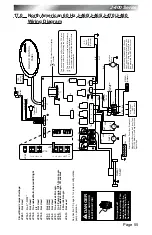
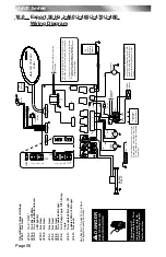
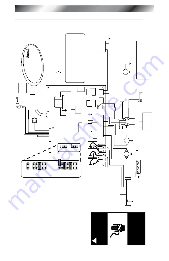
17.0 north american 60 Hz J-460/J-465/J-470/J-480
wiring Diagram
K13
J8
J6
J7
12V
AC Output Power to Lighting
Controller
.
T
ransformer
T1
K1
K2
K3
K4
K5
K6
J4
J3
K7
K8
Options
Sensors
LCD Panel
Flow
Switch
Hi-Limit/Freeze
Sensor
Temperature
Sensor
LED
Lighting
Controller
This device complies with Part 15 of the FCC rules.
Operation is subject to the following two conditions:
(1)
This device may not cause harmful interference.
(2)
This device must accept any interference
received including interference that may cause
undesired operation.
1 3 5 8 10
J2
J1
MAIN LCD CONTROL
P
ANEL
1
1
2
1
2
2
CD
Ozone
Generator
(Optional)
BLK
BLK
WHT
WHT
Circulation
Pump
Heater
5.5 kW
RED
RED
WHT
WHT
PUMP
1
PUMP
2
HI
HI
Z1
BLK
BLK
RED
RED
F1
30A, 250V
SC-30
To Heater Relays
TB1
TB3
TB1
TB2
TB6
TB4
STEREO (Optional)
Main Power
On/Of
f
Shutof
f Switch
GRN
External Service Panel Box - Disconnect
Means Must Be Located No Closer
Than
5FT
(1.52 Meters) From Edge
And Within
Sight of Spa.
240V
AC/60Hz, 23A/38A/45A, 1-Phase,
Use Copper Conductors Only
, Use Min.
8A
WG/75°C Wire Size, Wire Size Must
Be
Appropriate Per NEC
And/Or Local
Codes.
1
3
5
7
9
1
3
5
7
9
11
13
JP19
JP20
JP9
1
3
5
7
9
1
3
5
7
9
11
13
JP19
JP20
JP9
DANGER
T
urn power off
before servicing. This
task should only be
performed by a quali
-
fied technician.
!
RISK OF SHOCK OR
ELECTROCUTION!
Circuit Board Jumper
s
ettings:
JP20-1:
n
ot
u
sed
Jp
19-1:
o
n C°,
o
ff F°
JP19-3:
n
ot
u
sed
JP19-5:
On enables
m
ulti-Colored
le
D light
kit
JP19-7:
n
ot
u
sed
JP19-9:
n
ot
u
sed
JP9-1:
n
ot
u
sed
JP9-3:
n
ot
u
sed
JP9-5:
n
ot
u
sed
JP9-7:
On enables 60
a
l
ogic
Jp
9-9:
o
n 2-
p
ump
l
ogic,
o
ff 1-
p
ump
l
ogic
Jp
9-1
1:
o
n enables 30
a
l
ogic,
o
ff enables
50
a
or 60
a
l
ogic
JP9-13:
n
ot used
See Section 7.0, page
4 for jumper configuration
pump operation.

