background image

• J-495™

• J-480™ 

• J-470™ 

• J-465™ 

• J-425™ 

• J-415™

J-400™ COLLECTION

OWNER’S MANUAL

2530-442D Rev A

Summary of Contents for J - 495

Page 1: ... J 495 J 480 J 470 J 465 J 425 J 415 J 400 COLLECTION OWNER S MANUAL 2530 442D Rev A ...

Page 2: ...ires an annual bulb replacement to properly sanitize your water TO DECREASE RISK OF INFECTION OR DISEASE Always maintain your spa filter as outlined below to ensure healthy spa water Refer to pages 61 64 Sec 13 0 for additional information Required Filter Maintenance Your new spa is equipped with an advanced water filtration system that provides unsurpassed water quality To ensure maximum water qu...

Page 3: ...quirements 16 8 0 Spa Fill Up Procedure 18 9 0 Spa Features 23 9 1 J 495 Spa Features 23 9 2 J 495 Massage Waterfall Selector Diagram 24 9 3 J 495 Air Controls Diagram 25 9 4 J 480 Spa Features 26 9 5 J 480 Massage Waterfall Selector Diagram 27 9 6 J 480 Air Controls Diagram 28 9 7 J 470 Spa Features 29 9 8 J 470 Massage Waterfall Selector Diagram 30 9 9 J 470 Air Controls Diagram 31 9 10 J 465 Sp...

Page 4: ...ed Massage Action 50 12 0 Programming and Operation Instructions 50 12 1 Programming the Heating Mode 51 12 2 Programming the Primary Filter 52 12 3 Programming the Secondary Filter 53 12 4 Cleanup Cycle 54 12 5 Blow Out Cycle 54 12 6 Water Care Programming 54 12 7 Optional Wi Fi Setup 57 12 8 Locking the Spa 57 12 9 Programming the Time and Date 59 12 10 Programming the Language 60 12 11 Units Di...

Page 5: ... 78 17 0 Typical Spa Wiring Diagrams 80 17 1 Wiring diagram for North American 60 Hz Models Only 80 18 0 Circuit Board Wiring Diagrams 81 18 1 J415 J425 J465 J470 J480 Domestic 60Hz Wiring Diagram 81 18 2 J495 Domestic 60Hz Wiring Diagram 82 18 3 J415 J425 J465 J470 J480 Export 50Hz Wiring Diagram 83 18 4 J495 Export 50Hz Wiring Diagram 84 18 5 Dip Switch Settings 85 18 6 Single Service 50Hz Conne...

Page 6: ...J 400 ...

Page 7: ...red operation This equipment has been tested and found to comply with the limits for a Class B Digital Device pursuant to Part 15 of the FCC Rules These limits are designed to provide reasonable protection against harmful interference in a residential installation This equipment generates uses and can radiate radio frequency energy and if not installed and used in accordance with the instructions ...

Page 8: ...ad to drowning or severe injury Never use the spa unless all suction guards filter filter lid or skimmer assembly are installed to prevent body and or hair entrapment Never operate or use the spa if the filter filter lid or skimmer assembly are broken or any part of the skimmer assembly is missing Please contact your dealer or nearest service center for service The suction fittings and suction cov...

Page 9: ...GFCI as required by NEC Article 680 42 4 WARNING RISK OF SEVERE INJURY OR DEATH Extreme caution must be exercised to prevent diving or jumping into the spa or slipping and falling which could result in unconsciousness drowning or serious injury Remember that wet surfaces can be very slippery Never stand walk or sit on the top railing of the spa 5 WARNING RISK OF HYPERTHERMIA OVER HEATING CAUSING S...

Page 10: ...spa use may lead to unconsciousness with the possibility of drowning 7 WARNING RISK OF SEVERE INJURY OR DEATH Prolonged immersion in a spa may be injurious to your health Observe a reasonable time limit when using the spa Exposures at higher temperatures can cause high body temperature over heating Symptoms may include dizziness nausea fainting drowsiness and reduced awareness These effects could ...

Page 11: ... given supervision or instruction concerning use of the appliance by a person responsible for their safety 12 NOTE This spa is not intended nor designed to be used in a com mercial or public application The spa buyer shall determine whether there are any code restrictions on the use or installation of this spa since local code requirements vary from one locality to another Hot Tub Safety Literatur...

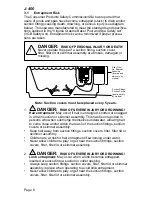
Page 12: ...r skimmer assembly This has been reported in persons who when submerge themselves underwater allowing hair to come close and or within the reach of the suction fittings suction covers or skimmer assembly Keep hair away from suction fittings suction covers filter filter lid or skimmer assembly Children are at risk for hair entrapment if swimming under water Never allow children to play or get near ...

Page 13: ... skimmer assembly Never allow children to play or get near the suction fittings suction covers filter filter lid or skimmer assembly 3 2 Hyperthermia Prolonged immersion in hot water may induce hyperthermia over heating The use of alcohol or drugs can greatly increase the risk of fatal hyperthermia in spas A description of the causes symptoms and effects of hyperthermia are as follows Hyperthermia...

Page 14: ...s rails ladders drains or other similar hardware within 10 feet 3m of the spa shall be bonded to the equipment grounding buss with copper conductors not smaller than No 6 AWG 10 mm 5 SAVE THESE INSTRUCTIONS 4 0 Choosing a Location IMPORTANT Because of the combined weight of the spa water and users it is extremely important that the base upon which the spa rests be smooth flat level and capable of ...

Page 15: ...st that you take into consideration The proximity to changing area and shelter especially in colder weather The pathway to and from your spa this should be free of debris so that dirt and leaves are not easily tracked into the spa The closeness to trees and shrubbery remember that leaves and birds could create extra work in keeping the spa clean A sheltered environment less wind and weather exposu...

Page 16: ...pa rests on has adequate drainage and can handle the entire contents of the spa Be sure to make provisions for ceilings and other structures that may be below the spas installation Areas around your spa can become wet or moist so all flooring and subsequent furniture walls and adjacent structures should be able to withstand or resist water and moisture Proper Ventilation Proper ventilation should ...

Page 17: ... illustrated Figure 4 3a Stand near the proposed front control panel side of the spa with your cell phone then login to the internet using your home Wi Fi router signal not 3G or 4G and verify results as follows If the home Wi Fi router signal is strong 3 4 bars and Internet access is stable the proposed installation site is a good choice If the home router s Wi Fi signal is weak and Internet acce...

Page 18: ...nstructions 240V Service IMPORTANT NOTICE The electrical wiring of this spa must meet the requirements of the National Electrical Code USA NEC and any applicable state or local codes The electrical circuit must be installed by a qualified electrician and approved by a local building electrical inspection authority 1 DANGER TO DECREASE THE RISK OF SHOCK PRODUCT DAMAGE OR ELECTRICAL FIRE This spa mu...

Page 19: ...0a Place the panel is a safe location to prevent damage 8 Select the power supply entrance you want to use Figure 6 0a Make sure to install a 3 4 electrical fitting and conduit through the large opening provided in the bottom of the control box so you can feed the cable through to the terminal block 9 Connect wires to the terminal block Figures 6 0b 6 0c ALL WIRES MUST BE SECURELY CONNECTED or equ...

Page 20: ... 4 S1 J7 J69 J68 1 Main Terminal Block 2 Bonding Lug Grounding Terminal 3 Power wires Entrance Electrical fitting and conduit must be installed Figure 6 0c Terminal Connections 2 1 3 Red Black F1 10A 250VAC F7 30A 30A F6 K12 K1 K9 K15 K14 T1 TB1 4 3 2 1 K5 J22 N A N A J43 J2 K13 J65 J51 J3 J52 J4 J61 J62 J49 K11 K10 J59 J44 J48 J39 2A 250VAC F5 30A F4 J28 J30 J27 J34 J29 J50 J56 J57 J63 J37 K8 K4 ...

Page 21: ...troller board must be changed depending on the number of breakers being used pages 89 and 90 Blu Brn N1 L1 TB1 TB3 Green Blu Blu Brn Brn Green L1 L2 N1 N2 TB1 TB3 Blu Brn Brn Brn Green L1 L2 N1 L3 TB1 TB3 Service 1 Service 2 Brn L2 Brn L1 Blu N2 Blu N1 Service 1 Service 2 Service 3 Brn L2 Brn L3 Brn L1 Blu N1 Factory Default Service 1 Brn L1 Blu N1 ...

Page 22: ...vice see table footnotes below Reference page 85 North American Models 60 Hz Voltage 240 VAC 40A 240 VAC 50A 240 VAC 60A Max Current Draw 1 Pump System 26A 36A N A 2 Pump System 26A 37A 48A 3 Pump System N A 37A 48A Frequency 60 Hz 60 Hz 60 Hz Number of Wires 3 3 3 In 40A configuration the heater will not operate while either jets pump is running Not recommended for the J495 In 50A configuration t...

Page 23: ...e 1 Pump System 2 Pump System 3 Pump System 3 5kW 3 9kW 6 7kW 5 1kW 6 7kW 8 3kW Frequency 50 Hz 50 Hz Number of Wires 3 3 Single breaker configuration is the factory default In this configuration the heater will not operate while any jets pump is running The service 1 breaker will include connection for all components In this configuration the heater will operate while one or two jets pumps are ru...

Page 24: ...ltage 230 VAC 230 VAC Max Current Draw 1 Pump System 2 Pump System 3 Pump System 12A 10A 12A 17A 12A 24A N A 12A 10A 7A 12A 10A 14A Wattage 1 Pump System 2 Pump System 3 Pump System 2 8kW 2 3kW 2 8kW 3 9kW 2 8kW 5 5kW N A 2 8kW 2 3kW 1 6kW 2 8kW 2 3kW 3 2kW Frequency 50 Hz 50 Hz Number of Wires 5 5 In this configuration the heater will operate while one or two jets pumps are running For 1 or 2 pum...

Page 25: ... OVERFILL IMPORTANT Always fill your spa through both filter fittings after draining Failure to do so may cause air to be trapped in the pumps preventing the pumps from circulating water Remove the hose and replace both filter cartridges as illustrated in Section 13 1 page 61 3 Turn On Power Turn on power to spa at the home s circuit breaker The heater and filter circulation pump will automaticall...

Page 26: ... Temperature feature that allows the spa to reach 106 F 41 C see page 77 Important Heater Details The maximum temperature for which the spa can be set is 104 F 40 C and the minimum is 80 F 27 C For North American spas With a 50 amp service turn off one of the jet pumps to operate heater With a 40 amp service turn off jet pump s to operate heater With a 60 amp service the heater will operate with t...

Page 27: ...0 450 Gal 1 703 L 11 0 oz J 480 480 Gal 1 817 L 12 0 oz J 495 560 Gal 2 120 L 14 0 oz Use average fill volume for chemical maintenance 2 Leave spa cover open during this step to allow excessive chemical vapors to exit spa protecting pillows and plastic knobs from chemical attack If spa is indoors open doors and windows for proper ventilation Turn on all spa jet pumps for one hour open all air cont...

Page 28: ...d for any reason while the cover is open and accessible to small children and animals To decrease the possibility of contracting a waterborne ill ness e g an infection bacteria or virus and or respiratory ailments maintain water chemistry within step 6 param eters If you or other bathers experience such a condition discontinue use and seek medical attention 7 Establish a sanitizer reading no less ...

Page 29: ...et Groups 4 Adjustable Pillows 4 ea 5 Lighted Cup Holders 4 ea 6 Massage Selectors 2 ea Controls Specified Jet Groups 7 Waterfalls 2 ea 8 FX Jets 18 ea 9 FX Rotational Jets 6 ea 10 MX2 Jets 3 ea 11 FX Large Rotational Jets 4 ea 12 FX Large Jet 1 ea 13 NX2 Jets 10 ea 14 FX Small Jets 8 ea 15 RX Jets 11 ea 16 Underwater Light 17 Footwell Filter Suction Covers 6 ea 18 Filter Skimmer Grill 19 Waterfal...

Page 30: ...jets groups 1a 1b Massage selector 2 diverts jets pump Nº 1 output between jets groups 2a 2b IX Jet Flow Control Valve 3 Valve 3 controls output to footwell IX Jet when jets pump Nº 3 is running Jets Without Massage Selector Controls 4 Jets 4 are always on when jets pump Nº 3 is running Waterfall Selector 5 Waterfall selector 5 controls circulation pump output to waterfall Spa operation subject to...

Page 31: ... 5 5 4 5 6 5 4 5 1 2 2 2 2 2 1 1 1 1 Air Controls Operation Rotate air controls 1 5 to add air to designated jet groups Center footwell IX Jet 6 draws air at all times when jets pump Nº 3 is running This jet has no air control Spa operation subject to change without notice ...

Page 32: ...lows 4 ea 6 Lighted Cup Holders 4 ea 7 Massage Selectors 2 ea Controls Specified Jet Groups 8 Waterfalls 2 ea 9 FX Jets 12 ea 10 FX Rotational Jets 6 ea 11 FX Small Jets 8 ea 12 Filter Skimmer Grill 13 MX2 Jets 3 ea 14 FX Large Rotational Jets 6 ea 15 NX2 Jets 4 ea 16 RX Jets 6 ea 17 Footwell Filter Suction Covers 4 ea 18 Waterfall Filtration Return 19 PX Jets 6 ea 20 Lighted IX Jet 21 Gravity Dra...

Page 33: ...s 1a 1b Massage selector 2 diverts output jets pump Nº 2 between jet groups 2a 2b Waterfall Selector 3 Waterfall selector 3 controls circulation pump output to waterfalls IX Jet Flow Control Valve 4 Valve 4 controls output to footwell IX Jet when jets pump Nº 2 is running Jets Without Massage Selector Controls 5 Jets 5 are always on when jets pump Nº 1 is running Spa operation subject to change wi...

Page 34: ...1 2 2 2 2 2 3 3 4 4 4 4 4 5 4 3 Air Controls Operation Rotate air controls 1 4 to add air to designated jet groups Center footwell IX Jet 5 draws air at all times when jets pump is running This jet has no air control Spa operation subject to change without notice ...

Page 35: ... 6 Lighted Cup Holders 4 ea 7 Massage Selectors 2 ea Controls Specified Jet Groups 8 Waterfalls 2 ea 9 RX Jets 6 ea 10 Filter Skimmer Grill 11 MX2 Jets 3 ea 12 FX Large Rotational Jets 4 ea 13 FX Large Jet 1 ea 14 NX2 Jets 4 ea 15 FX Jets 10 ea 16 FX Rotational Jets 6 ea 17 FX Small Jets 8 ea 18 Footwell Filter Suction Covers 4 ea 19 Waterfall Filtration Return 20 Lighted IX Jet 21 Gravity Drain H...

Page 36: ... 1a 1b Massage selector 2 diverts jets pump Nº 2 output between jet groups 2a 2b Waterfall Selector 3 Waterfall selector 3 controls circulation pump output to waterfalls IX Jet Flow Control Valve 4 Valve 4 controls output to footwell IX Jet when jets pump Nº 2 is running Jets Without Massage Selector Controls 5 Jets 5 are always on when jets pump Nº 1 is running Spa operation subject to change wit...

Page 37: ...1 1 1 2 2 3 3 4 4 4 3 1 1 5 Air Controls Operation Rotate air controls 1 4 to add air to designated jet groups Center footwell IX Jet 5 draws air at all times when jets pump is running This jet has no air control Spa operation subject to change without notice ...

Page 38: ... ea 6 Lighted Cup Holders 3 ea 7 Massage Selectors 2 ea Controls Specified Jet Groups 8 Waterfall 9 FX Jets 6 ea 10 FX Rotational Jets 6 ea 11 Filter Skimmer Grill 12 Footwell Filter Suction Covers 4 ea 13 NX2 Jets 4 ea 14 FX Large Rotational Jets 6 ea 15 FX Large Jet 1 ea 16 PX Jets 4 ea 17 RX Jets 6 ea 18 MX2 Jets 5 ea 19 Lighted IX Jet 20 Gravity Drain Heater Input CLEARRAY Return Fitting 21 Wa...

Page 39: ...jet groups 2a 2b Waterfall Selector 3 Waterfall selector 3 controls circulation pump output to waterfalls IX Jet Flow Control Valve 4 Valve 4 controls output to footwell IX Jet when jets pump Nº 1 is running Jets Without Massage Selector Controls 5 Jets 5 are always on when jets pump Nº 2 is running 100 6 45p ON 1a 1a 2a 2b 2b 2b 5 5 4 2b 1b 1b 1b 1 4 3 2 a b a b 3 Spa operation subject to change ...

Page 40: ... 1 2 1 2 2 2 2 2 2 3 3 4 1 1 2 Air Controls Operation Rotate air controls 1 3 to add air to designated jet groups Center footwell IX Jet 4 draws air at all times when jets pump is running This jet has no air control Spa operation subject to change without notice ...

Page 41: ...ied Jet Groups 7 Lighted Cup Holders 3 ea 8 Massage Selector 1 ea Controls Specified Jet Groups 9 MX2 Jets 3 ea 10 NX2 Jets 2 ea 11 RX Jets 2 ea 12 FX Rotational Jets 4 ea 13 FX2 Large Rotational Jets 3 ea 14 FX Large Jets 2 ea 15 Filter Skimmer Grill 16 Underwater Light 17 Footwell Filter Suction Covers 4 ea 18 Gravity Drain Heater Input CLEARRAY Return Fitting 19 Waterfall 20 Lighted IX Jet 21 W...

Page 42: ...º 1 output between jet groups 1a 1b IX Jet Flow Control Valve 2 Valve 2 controls output to footwell IX Jet when jets pump Nº 1 is running Waterfall Selector 3 Waterfall selector 3 controls circulation pump output to waterfall Jets Without Massage Selector Controls 4 Jets 4 are always on when jets pump Nº 2 is running Spa operation subject to change without notice ...

Page 43: ...N 4 4 5 1 1 3 2 2 2 1 2 4 3 Air Controls Operation Rotate air controls 1 4 to add air to designated jet groups Center footwell IX Jet 5 draws air at all times when jets pump is running This jet has no air control Spa operation subject to change without notice ...

Page 44: ... 1 ea Controls Specified Jet Groups 6 Integrated Cup Holders 2 ea 7 Adjustable Pillow 8 Optional Audio System Speakers 2 ea 9 RX Jets 5 ea 10 NX2 Jets 2 ea 11 Waterfall Control Valve 12 Waterfall 13 Filter Skimmer Grill 14 Footwell Filter Suction Covers 2 ea 15 Gravity Drain Heater Input CLEARRAY Return Fitting 16 FX Large Rotational Jet 1 ea 17 Waterfall Overflow 18 Underwater Light 19 Optional B...

Page 45: ...ram 100 6 45p ON 2 1a 1a 1a 1a 1b 1b 2 b a 1 Massage Selector 1 Massage selector 1 diverts output between jet groups 1a 1b Waterfall Selector 2 Waterfall selector 2 controls circulation pump output to waterfall Spa operation subject to change without notice ...

Page 46: ...age 40 J 400 9 18 J 415 Air Controls Diagram 100 6 45p ON 1 2 1 1 1 1 2 2 Air Controls Operation Rotate air controls 1 2 to add air to designated jet groups Spa operation subject to change without notice ...

Page 47: ...ill be able to activate components but after 10 minutes the screen will revert back to the registration screen This process will continue until the spa is registered and the passcode North American models only is entered Note The spa will still protect itself if an error is detected To register your spa you need to have your spa serial number The best time to retrieve the serial number is when the...

Page 48: ...ter your spa online you can then enter the registration information into the control panel Note If a number is entered wrong you can tap to move backwards 1 From the registration screen Figure 10 2a tap enter to enter the spa serial number 2 Input the 9 digit serial number Figure 10 2c If your serial number begins with a letter use the or buttons until the letter is displayed 3 Tap to enter and sa...

Page 49: ... Control Allows you to adjust the set temperature of the spa Increase the temperature by tapping in 1 increments Decrease the temperature by tapping in 1 increments Note The temperature range for the spa is 65 to 104 F 18 33 to 40 C To activate the Extended Temperature feature that allows the spa to reach 106 F 41 C see page 77 Jet Button Tap to access the menu to operate the jets pump page 44 Lig...

Page 50: ...a 12 Hour or 24 Hour configuration page 59 The default setting is 12 Hour Note The time does NOT automatically adjust for daylight saving time The time must be manually adjusted 11 0 Operating Instructions 11 1 ProTouch Control Panel Your Jacuzzi spa is equipped with a ProTouch control panel massage selectors and air control knobs located on the top rim of the spa pages 23 40 These controls let yo...

Page 51: ... pump s back on 11 3 Lights Menu From the Home Menu Figure 11 3a tap to enter the Light submenus The LCD screen will display the Light Submenu Figure 11 3b From this menu you can control the hot tub lighting When you tap to enter the submenu the lights will turn on if not on already in a color blending mode Default settings are brightness level at 0 and speed setting of 0 Note The lights automatic...

Page 52: ...els equipped with the optional Audio System offer an enhanced spa experience The BLUEWAVE 2 0 Wireless Audio System works with most Bluetooth wireless devices An auxiliary device can be connected via a 3 5 mm plug cable located behind the front cabinet panel if a Bluetooth device is not available These models also include four high fidelity spa engineered speakers for unsurpassed sound quality and...

Page 53: ...rward through tracks Rewind Tap to move back through tracks Pause Play Tap to pause and play tracks Track Name Artist Track Will display the artist and track information if it is available If the information is not available this part will be blank If the information provided is too long the maximum number of characters will be display follow by dots Audio Settings Tap to access the audio submenu ...

Page 54: ...ll be highlighted confirming the connection 5 If asked for a password enter the password 0000 and then connect 6 If the pairing process is successful your Bluetooth device will show Connected right next to BLUEWAVE The Bluetooth icon will be highlighted 11 6 Audio Settings Menu To enter the Audio Settings Menu tap from the Music submenu Figure 11 6a The display will change to Figure 11 6b The Audi...

Page 55: ...a programmed or scheduled setting the feature cannot be turned off 11 8 Adjusting Jet Flow The water flow to certain jets in your spa can be increased or decreased by rotating the outside jet face Note Always keep at least 6 adjustable jets open at all times 11 9 Adjusting PowerPro MX2 Jets Tilt PowerPro MX2 Jet nozzle to angle of choice as desired Rotate nozzle clockwise to reduce flow volume fro...

Page 56: ...d levels within the valve to vary between positions due to the large amounts of water flowing through it For optimum filtration benefits leave the valve in position A when spa is covered Select position B or C for maximum jet performance during spa use 11 14 Indicator Light The indicator light located on the front cabinet panel of the spa is an early detection system that will notify you when the ...

Page 57: ...w the selections available 12 1 Programming the Heating Mode Your Jacuzzi spa is equipped with 3 modes of heating Figure 12 1a An automatic mode called Auto where the spa s temperature is maintained at all times An energy saving heating cycle called Econo A mode that will only activate the heater during the daytime called Day mode Note The heater will activate when the temperature drops 2 from the...

Page 58: ...actory default cycle starts at 12 00 AM and last for 8 hours If you elect to keep this setting then you can skip this section In extreme bitter cold weather we recommend you program the circulation pump to run 24 hours Refer to the Winterizing section on page 68 Any time the circulation pump runs outside of a program cycle e g for heating that run time will be deducted from the next primary filter...

Page 59: ... for it s mandatory 2 hour cycle To help prevent a Summer Logic condition it may be necessary to reduce filter circulation pump cycles run times in warm weather 12 3 Programming the Secondary Filter To access the Secondary Filter feature tap 2 from the Heat Filter Menu Figure 12 3a to enter the Secondary Filter programming Figure 12 3b During a secondary filtration the Jets Pump 1 is activated The...

Page 60: ...ump 3 will turn on and run for 1 minute then shut off The feature can be deactivated by turning off the corresponding jets pump that is running This cycle will only occur at start up and after exiting a service lock 12 6 Water Care Programming Water care is crucial to maintaining a healthy and clean spa The CLEARRAY water purification system leads the way by sanitizing the water using a UV light b...

Page 61: ... Water Refresh 60 Figure 12 6b to enter the Programming Menu 1 From the Water Care Menu you can to set the Water Refresh timer Figure 12 6e 2 Tap or to change the days in 30 day increments The range is from OFF to 180 days Note It is not recommended that this feature be turned OFF In order to continually maintain the water healthy and clean in addition to chemical maintenance it should be program ...

Page 62: ... set to remind you when to replace the ProClarity Depth Filter Tap ProClarity Depth 50 Figure 12 6b to enter the Programming Menu 1 From the Water Care Menu you can to set the ProClarity Depth timer Figure 12 6i 2 Tap or to change the days in 10 day increments The range is from OFF to 90 days Note It is not recommended that this feature be turned OFF In order to continually maintain clean and work...

Page 63: ...ay will change to Spa Wi Fi Setup In progress and the reset button will be highlighted in Orange 3 Tap Reset again This will clear the current data and allow the spa to connect to the new data 4 Reconfigure and setup your spa by following the instructions from the app 12 8 Locking the Spa From the Settings Menu tap or to highlight the Lock menu tab in Orange Tap Lock Figure 12 8a to enter the prog...

Page 64: ...rn to the Settings Menu C Service Lock Figure 12 8b 1 Tap to lock the spa When this feature is activated all the lock buttons highlighted Orange 2 Tap block to select a number Use or to select a number from 0 9 Then move on to the next number until a four digit code has been selected 3 Tap to activate the locking feature 4 All spa functions are locked to allow for a temporary service mode for filt...

Page 65: ...ou must round a 12 Hour period 4 Tap the minute block 12 30 to program 5 Tap or to change the minutes 6 Tap to confirm and save your changes B To set the date Each setting for month day and year can be set independently 1 Tap Date to program the date Figure 12 9d 2 Tap the month block 1 30 2015 to program 3 Tap or to make changes 4 Tap the day block 1 30 2015 to program 5 Tap or to make changes 6 ...

Page 66: ...1 Tap next to the unit of measure that you want to display 2 Tap a few times to return to the Main Menu Heat Filter Language Units SETTINGS Fº Cº Units 12 12 System Information This menu will display the current information for the spa From the Settings Menu tap or to highlight the System Information Menu tab in Orange Tap System Information to enter the selection menu Figure 12 12a There are no s...

Page 67: ...n fitting or suction cover with one rated less than the flow rate marked on the original suction fitting Using improper suction fittings or suction covers can create a body or hair suction entrapment hazard that may lead to drown ing or severe injury Owners must alert all spa users to the potential risk of Hair Limb Body Evisceration disembowelment and Mechanical Entrapment page 6 13 1 Cleaning th...

Page 68: ... filter cleaning procedure The circulation pump filter goes on the side that has the wall fitting with the grids Figure 13 1b Note Do not attempt to wash the ProClarity depth filter B and the ProClear ProClarity debris bag E or it will come apart B Cleaning the Filters Debris bag A DANGER TURN POWER TO SPA OFF TO DECREASE RISK OF DEATH DROWNING OR ENTRAPMENT NEVER OPERATE SPA WHEN FILTER IS NOT PR...

Page 69: ...r H 1 2 3 Once the filter pins are removed rotate the filter cartridge handle counterclockwise to unthread from the filter canister You can clean the filter 1 and canister 3 but you must replace the ProClarity Depth Filter 2 every 3 months I Canister Cartridge 2 Rinse debris from filter pleats using a garden hose and high pressure nozzle Start at the top and work downward towards handle Repeat unt...

Page 70: ...ir entrapment during installation L Place each cartridge back into skimmer well then rotated each cartridge handle clockwise to thread back into wall fitting DO NOT OVERTIGHTEN M Install clean debris bag back onto the filter cover clips as shown you can flip the filter skimmer and use the back side to extend usage N Spa Shell Reinstall the skimmer shield over the filters Then turn power to spa bac...

Page 71: ...see WINTERIZING page 68 On the other hand if it is hot out doors do not leave the spa s surface exposed to direct sunlight A To drain your spa perform the following steps standard drain 1 Turn off power to spa at breaker 2 Locate the drain valve located on the front left corner on the black plastic pan Hold the larger rear drain valve body to prevent it from turning then loosen and remove the fron...

Page 72: ...he hot tub has drained close the slice valve by pushing it downward and sliding the handle to the side Remove the adapter and reinstall the QuickDrain cap before refilling hot tub 10 To reinstall the panel just follow the steps above in reverse order After refilling turn on power to the spa and follow the steps listed under Spa Fill Up Procedures page 18 Always fill your spa through both filter bu...

Page 73: ...ve and durable Regular monthly cleaning and conditioning vinyl is strongly recommended and may increase the longevity of your cover Jacuzzi chemicals are for use in the U S only A To clean and condition the encasement cover skin 1 Use a garden hose to remove any debris 2 Using a large sponge or soft bristle brush use diluted or mild soap to gently scrub the top 3 Rinse and clean and do not allow s...

Page 74: ...ge to the spa If you do not intend to use your spa or if there is a prolonged power outage during periods of severe freezing temperatures it is important that all water be removed from the spa and equipment to protect against damage from freezing Expert winterization of your spa is highly recommended contact your authorized Jacuzzi dealer In emergency situations taking the following steps can mini...

Page 75: ...nstall cabinet side panels and cover spa so that no casual moisture can enter into it Consult your Jacuzzi dealer if you have any questions regarding winter use or winterizing 13 9 Restarting Your Spa in Cold Weather If you want to start up your spa after it has sat empty for a time in freezing temperatures be aware that the water remaining in certain Sections of the piping may still be frozen Thi...

Page 76: ...r surface scaling In addition the ability of the sanitation agents to keep the spa clean is severely affected as the pH moves beyond the ideal range That is why almost all spa water test kits contain a measure for pH as well as sanitizer Jacuzzi offers products that help you maintain the ideal range These chemicals are for use in the U S only 14 2 Sanitizing To destroy bacteria and organic compoun...

Page 77: ...eria viruses and algae in portable spas The ultraviolet light otherwise known as UV C or germicidal light inactivates the microorganisms disrupting the DNA so that it cannot reproduce and is considered lifeless CLEARRAY is plumbed in line with your filtration system After the water is drawn from the pump filter and heater it is then directed though the CLEARRAY system Water passes through an ultra...

Page 78: ...nnection may vary by model 1 Turn the breaker to the spa OFF DRAIN YOUR SPA Note If you are only replacing the UV bulb then the spa does not have to be drained You will need to drain it if you are replacing or cleaning the quartz tube WARNINGS Do not operate the UV C emitter when it is removed from the appli ance enclosure This appliance contains a UV C emitter Unintended use of the appliance or d...

Page 79: ...ners as they can scratch the quartz tube surface 8 Rinse the quartz tube with clean water to completely remove any cleaning products that were used in step 7 9 Replacing quartz tube Remove the black o ring from the quartz tube and place it on the new tube Place the new quartz tube 8 into the water chamber 12 with the domed end first making sure it is inserted and seated inside the quartz end holde...

Page 80: ...ulb which contains mercury Dispose of the bulb in accordance with disposal laws See www lamprecycle org 19 Once power is activated you can check the ballast Figure 14 5g to see if the CLEARRAY System is functioning The power on red light indicates that the CLEARRAY System is being provided power and should always be on The lamp on green light indicates that UV bulb is activated 15 0 Error Display ...

Page 81: ...echnician 6 Open Water Temp Sensor The temperature sensor is not functional Heater is disabled This must be repaired only by a qualified authorized service organization or service technician 7 Shorted Ambient Temp Sensor The temperature sensor is not functional Heater is disabled This must be repaired only by a qualified authorized service organization or service technician Monitors the controller...

Page 82: ...that the spa is an overheat condition The heater icon will be blinking and the error icon will be dis played under the temperature 14 Watchdog Protection DO NOT ENTER SPA Water temperature is above acceptable limits Your spa is deactivated Remove spa cover to speed cooling If condition persists contact your authorized dealer or service organization Note The heater icon will be blinking and the err...

Page 83: ...Water Refresh timer has expired Figure 15 0g The water needs to be drained and refilled with fresh water 24 Extended Temperature Activated The spa is set to go up to 104 F 40 C but it can be set to reach 106 F 41 C To access the extended temperature you need press and hold your finger over the temperature reading for about 5 seconds The temperature reading will start to blink to indicate the syste...

Page 84: ...PUMP DOES NOT OPERATE Activate the JETS 1 If no sound is detected or if a buzzing sound is detected turn off power to the spa and contact your dealer or service center 2 If motor operates but no water flows to jets A Pump may not be properly primed See instructions below B Contact dealer or authorized service center Pump Priming Instructions 1 Turn off power to the spa 2 Remove the handle from the...

Page 85: ...tact your dealer or authorized service center FILTER CIRCULATION PUMP OFF 1 Verify filter circulation pump is programmed to run 8 hours a day page 49 2 Make sure there are no errors preventing the pump from turning on 3 Hot tub water is warmer than 95 F 34 C and two degrees warmer than the set temperature The Summer Logic safety feature has activated See note on page 53 for details Jacuzzi builds ...

Page 86: ... L2 240 VAC No Load Neutral Wire Note service disconnect not shown in this diagram Red L2 Red L2 Pigtail Neutral Bus Ground Black L1 Black L1 Green GFCI Sub Panel Main Panel 2 Pole GFCI Breaker Ground Bonding Lug No Load Neutral Wire Main Panel with Secondary GFCI Shut Off Box Using a 2 Pole GFCI Breaker with 2 Wire Grounded Connection 3 Wires to Hot Tub 2 Hot L1 L2 1 Ground White N Green Ground G...

Page 87: ...OW HI LIMIT TEMP J16 J17 J18 J1 J9 J11 J13 J14 J15 J10 J24 ZONE 2 J23 ZONE 1 J26 ZONE 4 C58 C57 K2 GFCI TRIP J8 Q32 HEATER J38 J53 J45 J46 J47 J41 J58 J42 J31 J32 J33 J40 J64 J36 J35 1 2 3 4 FUSE CIRC OZONE STATUS INDICATOR GRN J7 J69 J68 WI FI CONTROL PANEL FLOW SENSOR WATER SENSOR STEP LIGHT OPTIONAL BLUEWAVE STEREO CLEAR R AY STEREO POWER SUPPLY PUMP 2 LIGHTING EXPANSION PUMP 1 CIRC PUMP HI LIM...

Page 88: ... J16 J17 J18 J1 J9 J11 J13 J14 J15 J10 J24 ZONE 2 J23 ZONE 1 J26 ZONE 4 C58 C57 K2 GFCI TRIP J8 F2 F6 Q32 HEATER J66 J38 J53 J45 J46 J47 J41 J58 J42 J31 J32 J33 J40 J64 J36 J35 1 2 3 4 FUSE CIRC OZONE STATUS INDICATOR GRN J7 J69 J68 WI FI CONTROL PANEL FLOW SENSOR WATER SENSOR BLUEWAVE STEREO CLEAR R AY STEREO POWER SUPPLY PUMP 2 PUMP 1 CIRC PUMP HI LIMIT SENSOR 240 VAC 26A 37A 48A 3 WIRE CONNECTI...

Page 89: ...WATER TEMP SERIAL ADCM FLOW HI LIMIT TEMP J16 J17 J18 J1 J9 J11 J13 J14 J15 J10 J24 ZONE 2 J23 ZONE 1 J26 ZONE 4 C58 C57 K2 GFCI TRIP J8 Q32 HEATER J38 J53 J45 J46 J47 J41 J58 J42 J31 J32 J33 J40 J64 J36 J35 1 2 3 4 FUSE CIRC OZONE STATUS INDICATOR GRN J7 J69 J68 WI FI CONTROL PANEL FLOW SENSOR WATER SENSOR BLUEWAVE STEREO CLEAR R AY STEREO POWER SUPPLY PUMP 2 PUMP 1 CIRC PUMP HI LIMIT SENSOR STAT...

Page 90: ...J15 J10 J24 ZONE 2 J23 ZONE 1 J26 ZONE 4 C58 C57 K2 GFCI TRIP J8 Q32 HEATER J66 J38 J53 J45 J46 J47 J41 J58 J42 J31 J32 J33 J40 J64 J36 J35 1 2 3 4 S1 FUSE CIRC OZONE STATUS INDICATOR GRN J7 J69 J68 WI FI CONTROL PANEL FLOW SENSOR WATER SENSOR BLUEWAVE STEREO CLEAR R AY STEREO POWER SUPPLY PUMP 2 PUMP 1 CIRC PUMP HI LIMIT SENSOR STATUS INDICATOR LEDS 230 VAC 50Hz Single Service 36A Dual Service 12...

Page 91: ...F OFF OFF OFF OFF 50A OFF OFF ON OFF OFF OFF OFF OFF OFF OFF 60A OFF OFF OFF ON OFF OFF OFF OFF OFF OFF 50A is the factory default setting DOMESTIC DIP SWITCH SETTINGS S1 LOCATION 40A 50A factory default 60A 1 2 3 4 5 6 7 8 9 10 OFF OFF ON OFF OFF OFF OFF OFF OFF OFF ON OFF 1 2 3 4 5 6 7 8 9 10 OFF OFF OFF ON OFF OFF OFF OFF OFF OFF ON OFF 1 2 3 4 5 6 7 8 9 10 OFF OFF OFF OFF OFF OFF OFF OFF OFF O...

Page 92: ...ATION 1x40A or 1x16A 1x32A 1x16A 1x20A 3x16A 1 2 3 4 5 6 7 8 9 10 ON OFF ON OFF ON OFF OFF OFF OFF OFF ON OFF 1 2 3 4 5 6 7 8 9 10 ON OFF OFF ON OFF OFF OFF OFF OFF OFF ON OFF 1 2 3 4 5 6 7 8 9 10 ON OFF OFF OFF ON OFF OFF OFF OFF OFF ON OFF BREAKER DIP SWITCH NUMBER 1 2 3 4 5 6 7 8 9 10 1x16A ON OFF OFF OFF OFF OFF OFF OFF OFF OFF 1x20A ON OFF OFF ON ON OFF OFF OFF OFF OFF 2x16A ON OFF ON OFF OFF...

Page 93: ...or all two pump model spas Both pumps and the heater will be allowed to operate at the same time Three Phase Service 3x16A This setting is for all two pump model spas Both pumps and the heater will be allowed to operate at the same time D Configuration settings for J495 Models Single Service default setting 1x32A This setting will allow the heater to operate when two jets pumps are activated If al...

Page 94: ... 4 3 BREAKER TERMINAL CONNECTIONS L1 All Components J415 J425 J465 J470 J480 Single Service Jumper Wiring Wire From To 1 J33 J47 2 J37 J36 3 J46 J51 4 J59 J41 Install extra white wire at these jumpers J495 Single Service Jumper Wiring Wire From To 1 J33 J47 2 J37 J36 3 J45 J61 4 J46 J51 5 J59 J41 6 J65 J40 Install extra white wire at these jumpers BREAKER TERMINAL CONNECTIONS L1 All components TB1...

Page 95: ...5 J465 J470 J480 Two Service Jumper Wiring Wire From To 1 J33 J51 2 J37 J53 3 J59 J38 TB1 D C B A J51 J49 J59 J44 J37 J38 J53 J45 J46 J66 J47 J41 J58 J42 J31 J32 J33 J40 J64 J36 J35 1 2 3 4 GRN N2 BLU L1 BRN N1 BLU L2 BRN DUAL SERVICE 1 2 3 J495 Two Service Jumper Wiring Wire From To 1 J33 J51 2 J37 J53 3 J59 J38 4 J61 J32 5 J66 J65 TB1 D C B A J51 J49 J59 J44 J37 J38 J53 J45 J46 J47 J41 J58 J42 J...

Page 96: ...C B A J51 J49 J59 J44 J37 J38 J53 J45 J46 J47 J41 J58 J42 J31 J32 J33 J40 J64 J36 J35 1 2 3 4 GRN L3 BRN L1 BRN N1 BLU L2 BRN THREE SERVICE J66 1 2 3 BREAKER TERMINAL CONNECTIONS L1 Heater and transformer L2 Pump 1 and other components L3 Pump 2 TB1 D C B A J51 J49 J59 J44 J37 J38 J53 J45 J46 J47 J41 J58 J42 J31 J32 J33 J40 J64 J36 J35 1 2 3 4 GRN L3 BRN L1 BRN N1 BLU L2 BRN THREE SERVICE J65 J61 ...

Reviews: