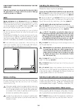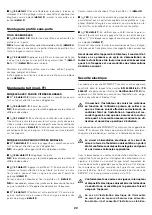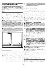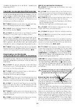
I
(
i
44 detail 2
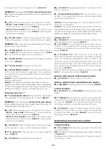
) Then fasten the profile to the shower tray, so
that it lines up with the profiles of glass panels “I” (
detail 2a
) and
“H” (
detail 2b
) as shown.
Keep the profile in position with sticky tape, until the silicone is
completely dry.
Finally, apply silicone to the base of the profile, as shown in
de-
tail 2a.
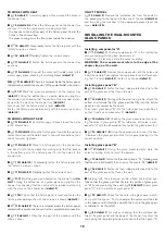
Assembling the top cover (for TT model)
MODELS WITH WALL-MOUNTED GLASS PANELS
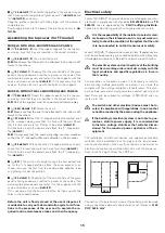
I
(
i
45 detail 1-2
) Insert the rubber supports for the top cov-
er, making sure that they are inserted in the correct direction.
I
(
i
46 detail 1-2
) Then insert the seals.
N.B.:
Make sure that the seal to be attached to the door is dif-
ferent to the others.
I
(
i
51 detail 1
) Checking that the smooth side of the glass
panel is facing downwards, rest the top cover on the seals of the
wall-mounted glass panels and fasten it to the supports with the
cams and screws as shown (
detail 2
). If it is necessary, turn the
cams so that the slot lines up with the holes in the supports.
MODELS WITHOUT WALL-MOUNTED GLASS PANELS
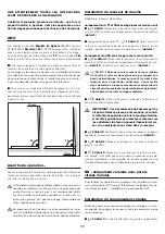
I
(
i
46A detail 1
) Insert the rubber supports for the top cov-
er, making sure that they are inserted in the correct direction.
N.B.
Part of the support must be removed and thrown away.
I
(
i
46A details 1-2
) Attach the seals.
N.B.
Make sure that the seal to be attached to the door is dif-
ferent to the others.
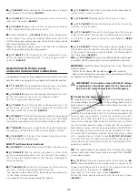
I
(
i
47 detail 1
) Rest the “L”-shaped profile (the shortest one)
on the crossbar, making sure that it is flush with the wall. Check
that it is level and mark the 3 holes to be drilled (
detail 2
).
Drill the holes, insert the dowels and attach the “L"-shaped pro-
file (
detail 3
).
N.B.
If necessary, trim the seals projecting over the crossbar,
so that the “L” -shaped profile rests directly on the crossbar.
I
(
i
48 detail 1
) Place the other “L”-shaped profile as shown,
check that it is level and mark the holes for drilling (
detail 2
).
Drill the holes, insert the dowels and attach the “L"-shaped pro-
file (
detail 3
).
I
(
i
49
) If the wall is not straight enough to allow perfect line
up for the "L"-shaped profiles, attach the cover bracket A, as
shown, removing the film from the double-sided adhesive tape
and glueing it under the profiles.
I
(
i
50 detail 1
) Checking that the smooth side of the glass
panel is facing downwards, rest the top cover on the seals of the
wall-mounted glass panels and fasten it to the supports with the
cams and screws as shown (
detail 2
).
If it is necessary, turn the cams so that the slot lines up with the
holes in the supports below.
Before the unit is finally placed at the user's disposal, it
is advisable to carry out a demonstration cycle for all func-
tions in the presence of the user and to explain the re-
quired routine maintenance tasks and their frequency.
Electrical safety
Jacuzzi
®
MYNIMA TT shower enclosures are safe appliances, man-
ufactured in compliance with standards
EN 60335.2.60
and
TS
2000/01
and are approved by the
T.Ü.V Certifying Institute.
These are tested during production to guarantee user safety.
몇
It is the responsibility of the installer to select materi-
als based on their intended use, to carry out work cor-
rectly, to check the condition of the system that the unit
is to be connected to so that it ensures user safety.
Jacuzzi
®
MYNIMA TT shower enclosures are Class “
I
” appliances, and
must be anchored securely and connected permanently, without any
intermediate connections, to the electric network and earth system.
몇
The electric system and earth system of the building
must be in working order and must comply with the
legal provisions and specific regulations in force in
that country.
For connection to the electric mains, it is necessary to install a
disconnecting multiple-pole switch, and place it in an area that
complies with the safety prescriptions for bathrooms. This stan-
dard multiple-pole switch must guarantee a contact opening of at
least 3mm, and be suitable for voltages of 220-240V and cur-
rents up to 16A.
몇
The switch and other electrical devices must be lo-
cated, in compliance with regulations, in an area that
cannot be reached by the person using the appliance.
몇
If the building’s electrical system is not able to gua-
rantee a stabile power supply, it is recommended
to install a voltage stabiliser that suitably dimen-
sioned for the required power upstream of the e-
quipment.
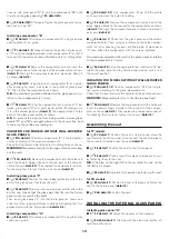
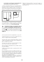
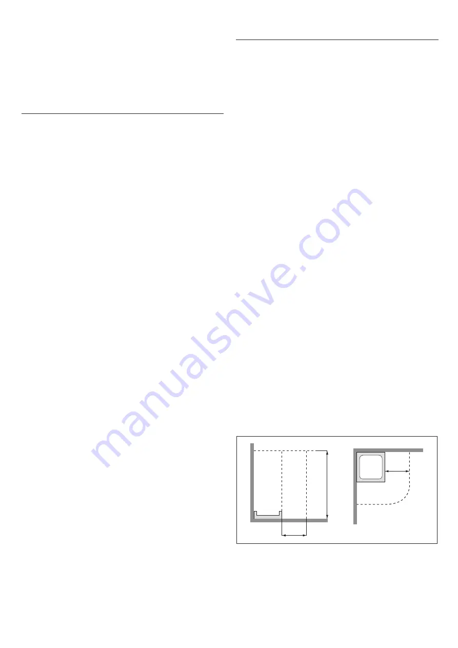
The installation of electrical devices and appliances (sockets,
switches, etc.) in bathrooms must comply with the legal require-
ments and standards of the country concerned. In particular, no
electrical installation is permitted within 60 cm of the shower en-
closure or at a height of less than 225 cm.
Connection to the electrical system of the building must be made
using a sheathed cable with characteristics not inferior to
H 05
VV-F 3x2.5 mm
2
.
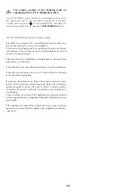
0,6 m
0,6 m
2,25
m
15


