-103-
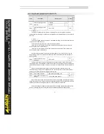
4.12 PID functions:PA.00-PA.28
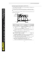
PID control is a general process control method. By performing proportional, integral and differential
operations on the difference between the feedback signal and the target signal, it adjusts the output
frequency and constitutes a feedback system to stabilize the controlled counter around the target value.
It is applied to process control such as flow control, pressure control and temperature control. The
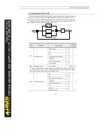
following figure shows the principle block diagram of PID control.
Code
Description
Setting range
Defa
ult
Restric
tions
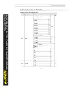
PA.00
PID setting source
PA.01 setting
0
0
☆
AI1
1
AI2
2
AI3( keyboard potentiometer)
3
Pulse(DI5)
4
Communication setting
5
Multi-reference
6
PA.01
PID digital setting
0.0%~100.0%
50.0%
☆
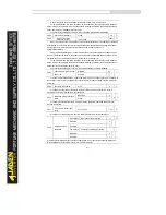
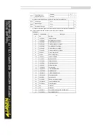
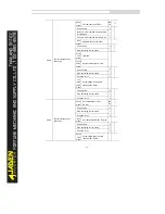
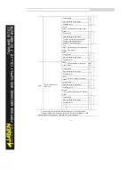
PA.00 is used to select the channel of target process PID setting. The PID setting is a relative
value and ranges from 0.0% to 100.0%. The PID feedback is also a relative value. The purpose of
PID control is to make the PID setting and PID feedback equal.
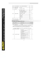
PA.02
PID feedback source
AI1
0
0
☆
AI2
1
AI3( keyboard potentiometer)
2
Pulse(DI5)
3
Communication setting
4
AI1
5
AI1+AI2
6
MAX(|AI1|, |AI2|)
7
+
-
Target
Feedback
PID output
P
1
Td*s+1
Ti
S
1
1
Summary of Contents for DLB1-0D40S2G
Page 11: ...11 Graph 1 722 30KW product outline dimensions Graph 1 837 55KW product outline dimensions...
Page 12: ...12 Graph 1 875 110KW product outline dimensions Graph 1 9 132 160KW product outline dimensions...
Page 14: ...14 2 Wirings 2 1 Standard wiring diagrams Graph 2 8 0 4 18 5KW inverter wiring diagram...
Page 15: ...15 Graph 2 922 400KW inverter wiring diagram...
Page 159: ...159...

