-104-
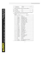
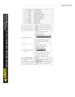
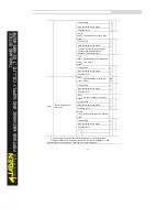
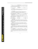
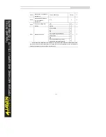
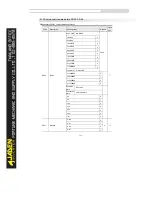
MIN(|AI1|, |AI2|)
8
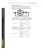
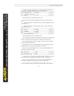
This parameter is used to select the feedback signal channel of process PID. The PID feedback
is a relative value and ranges from 0.0% to 100.0%.
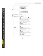
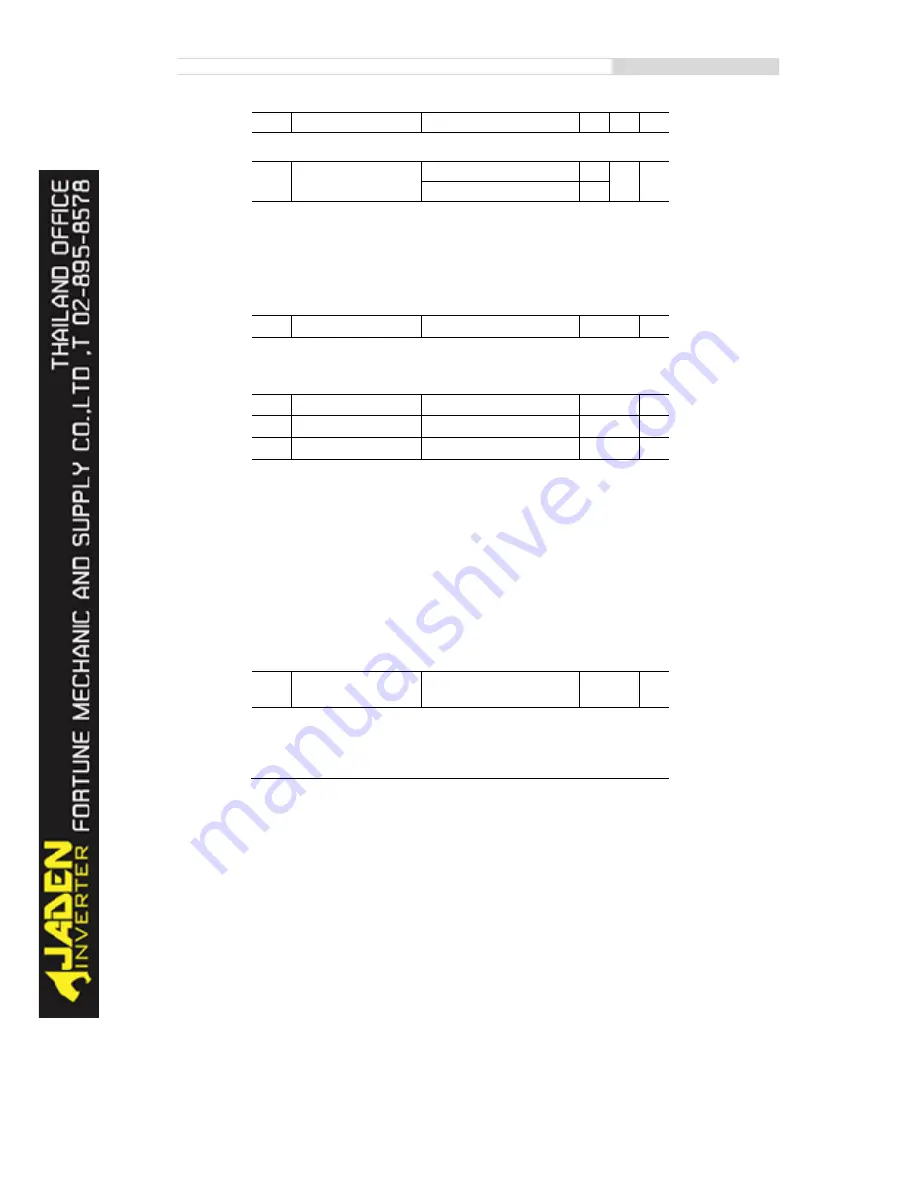
PA.03
PID action direction
Forward action
0
0
☆
Reverse action
1
•
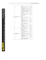
0: Forward action
When the feedback value is smaller than the PID setting, the Inverter's output frequency rises.
For example, the winding tension control requires forward PID action.
•
1: Reverse action
When the feedback value is smaller than the PID setting, the Inverter's output frequency
reduces. For example, the unwinding tension control requires reverse PID action.
Note that this function is influenced by the DI function 35 "Reverse PID action direction"
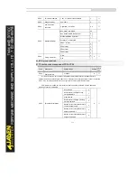
PA.04
PID feedback range
0~65535
1000
☆
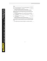
This parameter is a non-dimensional unit. It is used for PID setting display (d0.15) and PID
feedback display (U0-16).
Relative value 100% of PID setting feedback corresponds to the value of PA.04. If PA.04 is set
to 2000 and PID setting is 100.0%, the PID setting display (d0.15) is 2000.
PA.05
Proportional gainK
p1
0.0~100.0
20.0
☆
PA.06
Integral timeTi
1
0.01s~10.00s
2.00s
☆
PA.07
Differential timeTd
1
0.00~10.000
0.000s
☆
l
proportional gainK
p1
:
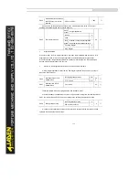
It decides the regulating intensity of the PID regulator. The higher the Kp1 is, the larger the
regulating intensity is. The value 100.0 indicates when the deviation between PID feedback and PID
setting is 100.0%, the adjustment amplitude of the PID regulator on the output frequency reference
is the maximum frequency.
l
integral timeTi
1
:
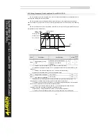
It decides the integral regulating intensity. The shorter the integral time is, the larger the
regulating intensity is. W hen the deviation between PID feedback and PID setting is 100.0%, the
integral regulator performs continuous adjustment for the time set in PA. 06. Then the adjustment
amplitude reaches the maximum frequency.
l
differential timeTd1:
It decides the regulating intensity of the PID regulator on the deviation change. The longer the
differential time is, the larger the regulating intensity is. Differential time is the time within which the
feedback value change reaches 100.0%, and then the adjustment amplitude reaches the maximum
frequency.
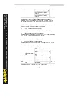
PA.08
Cut-off frequency of PID
reverse rotation
0
.
00~ maximum frequency
2.00Hz
☆
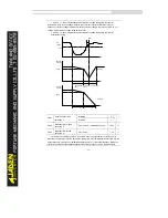
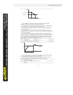
In some situations, only when the PID output frequency is a negative value (Inverter reverse
rotation), PID setting and PID feedback can be equal. However, too high reverse rotation frequency
is prohibited in some applications, and PA.08 is used to determine the reverse rotation frequency
upper limit.
Summary of Contents for DLB1-0D40S2G
Page 11: ...11 Graph 1 722 30KW product outline dimensions Graph 1 837 55KW product outline dimensions...
Page 12: ...12 Graph 1 875 110KW product outline dimensions Graph 1 9 132 160KW product outline dimensions...
Page 14: ...14 2 Wirings 2 1 Standard wiring diagrams Graph 2 8 0 4 18 5KW inverter wiring diagram...
Page 15: ...15 Graph 2 922 400KW inverter wiring diagram...
Page 159: ...159...

