-105-
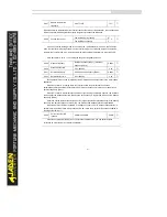
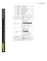
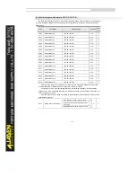
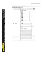
PA.09
PID deviation limit
0.0%~100.0%
0.0%
☆
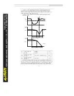
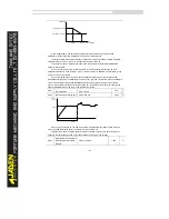
If the deviation between PID feedback and PID setting is smaller than the value of PA.09, PID
control stops. The small deviation between PID feedback and PID setting will make the output
frequency stabilize, effective for some closed-loop control applications.
PA.10
PID differential limit
0
.
00%~100.00%
0.10%
☆
It is used to set the PID differential output range. In PID control, the differential operation may
easily cause system oscillation. Thus, the PID differential regulation is restricted to a small range.
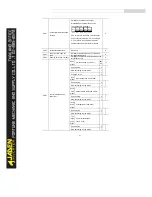
PA.11
PID setting change time
0.00s~650.00s
0.00s
☆
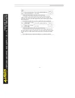
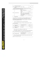
The PID setting change time indicates the time required for PID setting changing from 0.0% to
100.0%. The PID setting changes linearly according to the change time, reducing the impact caused
by sudden setting change on the system.
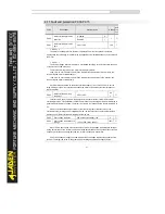
PA.12
PID feedback filter time
0.00s~60.00s
0.00s
☆
PA.13
PID output filter time
0.00s~60.00s
0.00s
☆
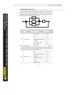
PA.12 is used to filter the PID feedback, helping to reduce interference on the feedback but
slowing the response of the process closed-loop system.
PA.13 is used to filter the PID output frequency, helping to weaken sudden change of the Inverter
output frequency but slowing the response of the process closed-loop system.
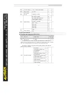
PA.14
Reserved
-
-
-
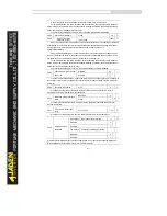
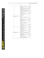
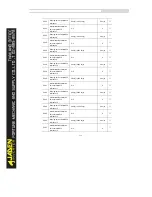
PA.15
Proportional gainK
p2
0.0~100.0
20.0
☆
PA.16
Integral timeTi
2
0.01s~10.00s
2.00s
☆
PA.17
Differential timeTd
2
0.00~10.000
0.000
s
☆
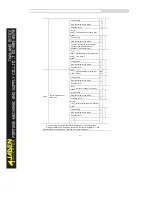
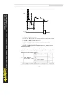
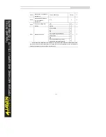
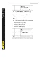
PA.18
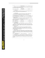
PID parameter switchover
condition
No switchover
0
0
☆
Switchover via DI
1
Automatic switchover based on
deviation
2
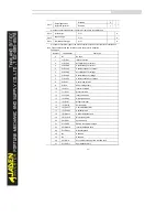
PA.19
PID parameter switchover
deviation 1
0.0%~PA.20
20.0%
☆
PA.20
PID parameter switchover
deviation 2
PA.19~100.0%
80.0%
☆
Summary of Contents for DLB1-0D40S2G
Page 11: ...11 Graph 1 722 30KW product outline dimensions Graph 1 837 55KW product outline dimensions...
Page 12: ...12 Graph 1 875 110KW product outline dimensions Graph 1 9 132 160KW product outline dimensions...
Page 14: ...14 2 Wirings 2 1 Standard wiring diagrams Graph 2 8 0 4 18 5KW inverter wiring diagram...
Page 15: ...15 Graph 2 922 400KW inverter wiring diagram...
Page 159: ...159...

