-106-
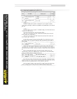
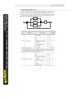
In some applications, PID parameters switchover is required when one group of PID
parameters cannot satisfy the requirement of the whole running process.
These parameters are used for switchover between two groups of PID parameters. Regulator
parameters PA.15 to PA.17 are set in the same way as PA.05 to PA.07.
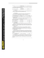
The switchover can be implemented either via a DI terminal or automatically implemented
based on the deviation.
If you select switchover via a DI terminal, the DI must be allocated with function 43 "PID
parameter switchover". If the DI is OFF, group 1 (PA.05 to PA.07) is selected. If the DI is ON, group
2 (PA.15 to PA.17) is selected.
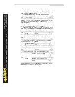
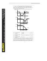
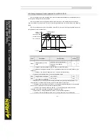
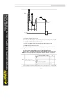
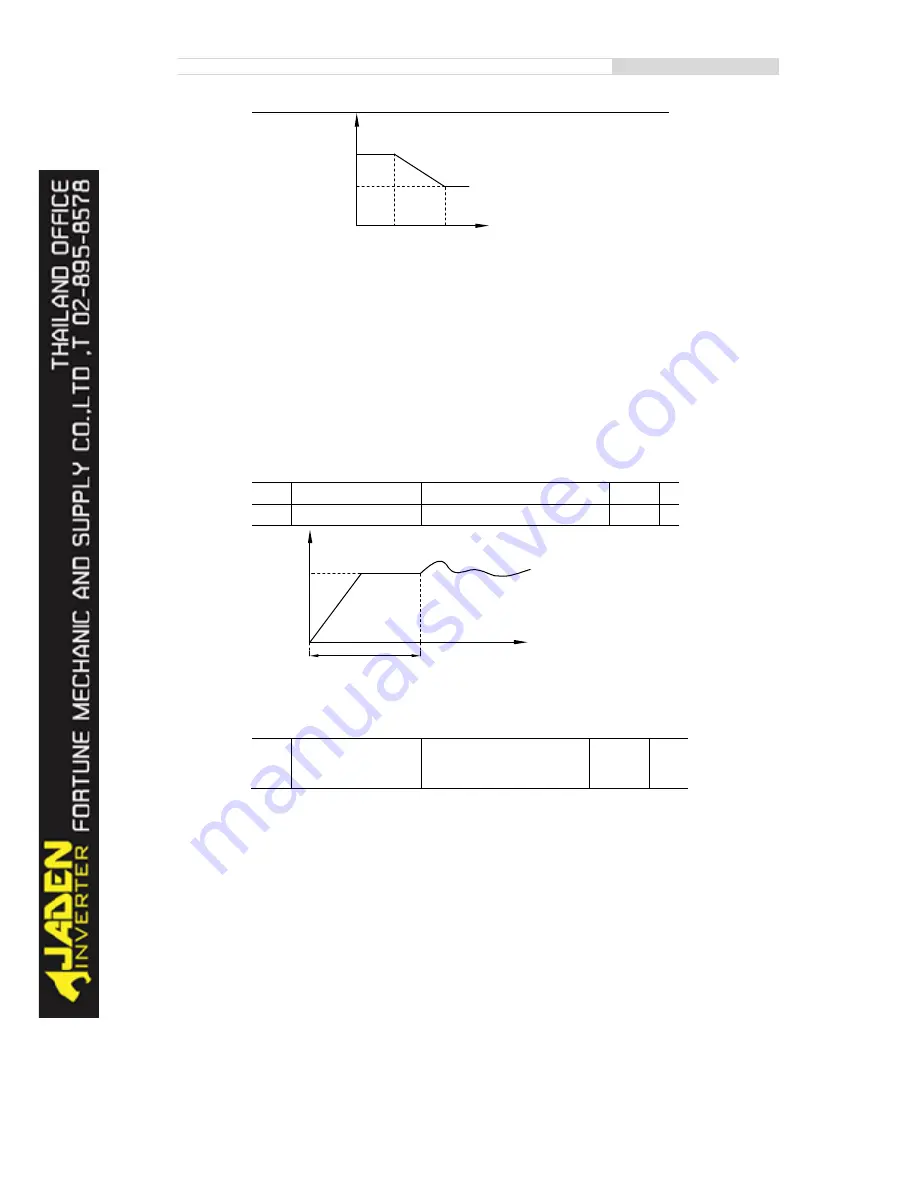
If you select automatic switchover, when the absolute value of the deviation between PID
feedback and PID setting is smaller than the value of PA.19, group 1 is selected. When the absolute
value of the deviation between PID feedback and PID setting is higher than the value of PA.20,
group 2 is selected. When the deviation is between PA.19 and PA.20, the PID parameters are the
linear interpolated value of the two groups of parameter values.
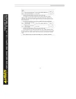
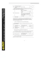
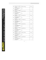
PA.21
PID initial value
0.0%~100.0%
0.0%
☆
PA.22
PID initial value holding time
0.00s~650.00s
0.00s
☆
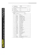
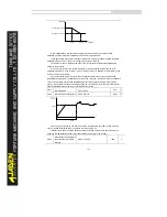
When the Inverter starts up, the PID starts closed-loop algorithm only after the PID output is
fixed to the PID initial value (PA.21) and lasts the time set in PA.22.
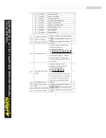
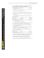
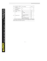
This function is used to limit the deviation between two PID outputs (2 ms per PID output) to
suppress the rapid change of PID output and stabilize the running of the Inverter.
PA.23
Maximum deviation between
two PID outputs in forward
direction
0.00%~100.00%
1.00%
☆
Output
Frequency
t
PA.21
PA.22
PA.19
PA.20
PID deviation
Parameters
PA.05
、
PA.06
、
PA.07
PA.15
、
PA.16
、
PA.17
Summary of Contents for DLB1-0D40S2G
Page 11: ...11 Graph 1 722 30KW product outline dimensions Graph 1 837 55KW product outline dimensions...
Page 12: ...12 Graph 1 875 110KW product outline dimensions Graph 1 9 132 160KW product outline dimensions...
Page 14: ...14 2 Wirings 2 1 Standard wiring diagrams Graph 2 8 0 4 18 5KW inverter wiring diagram...
Page 15: ...15 Graph 2 922 400KW inverter wiring diagram...
Page 159: ...159...

