-112-
•
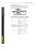
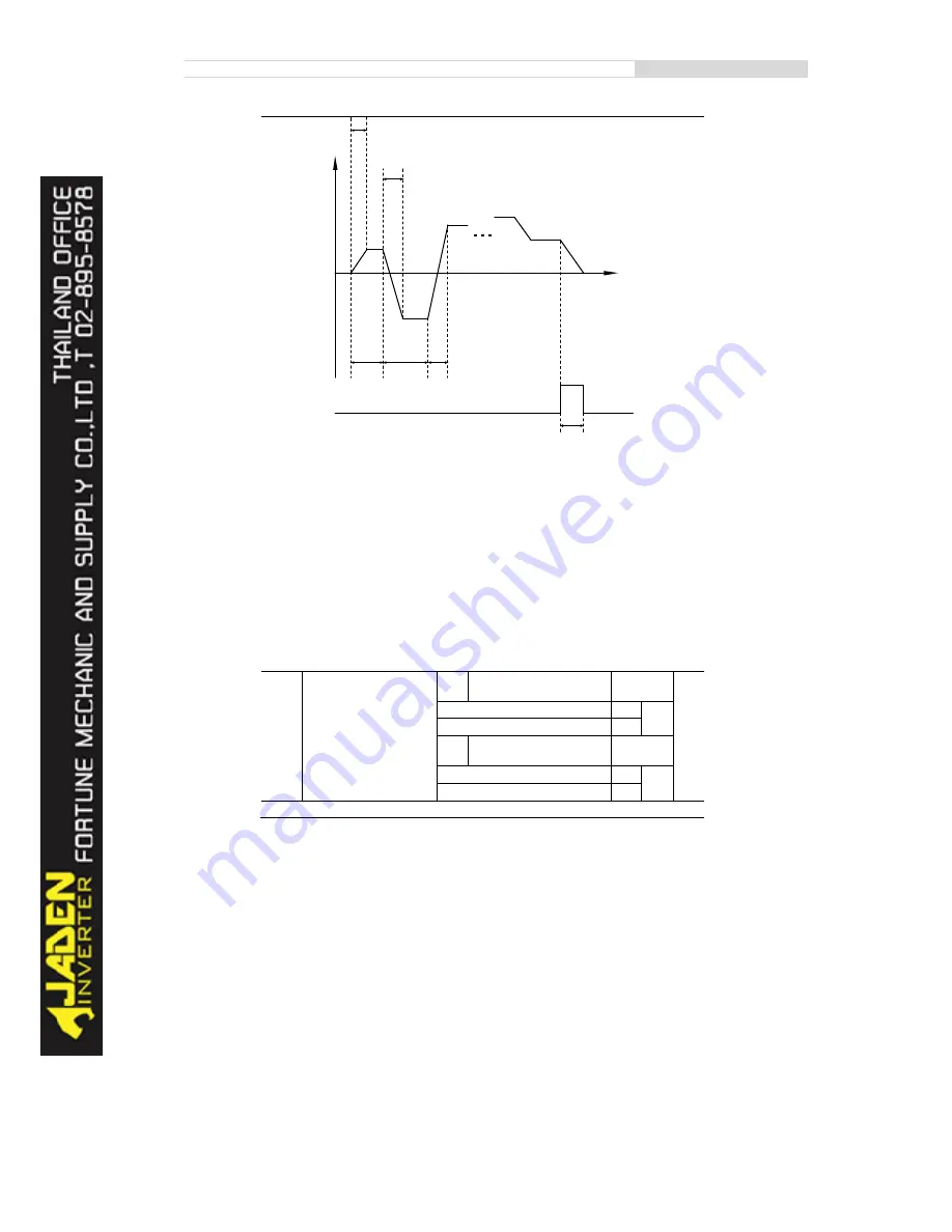
0: Stop after the Inverter runs one cycle
The Inverter stops after running one cycle, and will not start up until receiving another command.
•
1: Keep final values after the Inverter runs one cycle
The Inverter keeps the final running frequency and direction after running one cycle.
•
2: Repeat after the Inverter runs one cycle
The Inverter automatically starts another cycle after running one cycle, and will not stop until
receiving the stop command.
Simple PLC can be either the frequency source or V/F separated voltage source.
When simple PLC is used as the frequency source, whether parameter values of PC.00 to PC.15
are positive or negative determines the running direction. If the parameter values are negative, it
indicates that the Inverter runs in reverse direction.
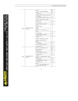
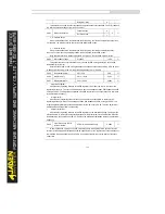
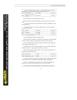
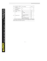
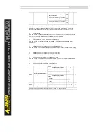
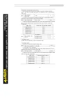
PC.17
Simple PLC retentive
selection upon power failure
One’s
place
Retentive upon power failure
00
☆
No
0
Yes
1
Ten’s
place
Retentive upon stop
No
0
Yes
1
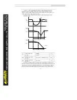
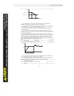
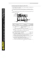
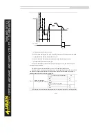
PLC retentive upon power failure indicates that the Inverter memorizes the PLC running moment
running
direction
PC.00
PC.21
PC.01
PC.18
PC.20
PC.23
PC.02
PC.14
PC.15
250ms pulse
time t
DO
or RELAY
Output
PC.19
Summary of Contents for DLB1-0D40S2G
Page 11: ...11 Graph 1 722 30KW product outline dimensions Graph 1 837 55KW product outline dimensions...
Page 12: ...12 Graph 1 875 110KW product outline dimensions Graph 1 9 132 160KW product outline dimensions...
Page 14: ...14 2 Wirings 2 1 Standard wiring diagrams Graph 2 8 0 4 18 5KW inverter wiring diagram...
Page 15: ...15 Graph 2 922 400KW inverter wiring diagram...
Page 159: ...159...

