-113-
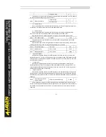
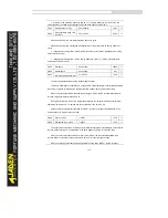
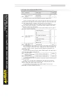
and running frequency before power failure and will continue to run from the memorized moment after
it is powered on again. If the unit's digit is set to 0, the Inverter restarts the PLC process after it is
powered on again.
PLC retentive upon stop indicates that the Inverter records the PLC running moment and running
frequency upon stop and will continue to run from the recorded moment after it starts up again. If the
ten's digit is set to 0, the Inverter restarts the PLC process after it starts up again.
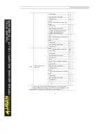
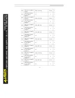
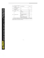
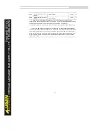
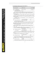
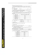
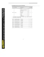
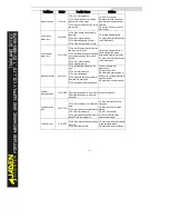
PC.18
Running time of simple PLC
reference 0
0.0s(h)~6553.5s(h)
0.0s(h)
☆
PC.19
Acceleration/deceleration
time of simple PLC
reference 0
0~3
0
☆
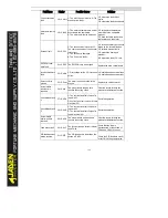
PC.20
Running time of simple PLC
reference 1
0.0s(h)~6553.5s(h)
0.0s(h)
☆
PC.21
Acceleration/deceleration
time of simple PLC
reference 1
0~3
0
☆
PC.22
Running time of simple PLC
reference 2
0.0s(h)~6553.5s(h)
0.0s(h)
☆
PC.23
Acceleration/deceleration
time of simple PLC
reference 2
0~3
0
☆
PC.24
Running time of simple PLC
reference 3
0.0s(h)~6553.5s(h)
0.0s(h)
☆
PC.25
Acceleration/deceleration
time of simple PLC
reference 3
0~3
0
☆
PC.26
Running time of simple PLC
reference 4
0.0s(h) ~6553.5s(h)
0.0s(h)
☆
PC.27
Acceleration/deceleration
time of simple PLC
reference 4
0~3
0
☆
PC.28
Running time of simple PLC
reference 5
0.0s(h) ~6553.5s(h)
0.0s(h)
☆
PC.29
Acceleration/deceleration
time of simple PLC
reference 5
0~3
0
☆
PC.30
Running time of simple PLC
reference 6
0.0s(h) ~6553.5s(h)
0.0s(h)
☆
PC.31
Acceleration/deceleration
time of simple PLC
reference 6
0~3
0
☆
Summary of Contents for DLB1-0D40S2G
Page 11: ...11 Graph 1 722 30KW product outline dimensions Graph 1 837 55KW product outline dimensions...
Page 12: ...12 Graph 1 875 110KW product outline dimensions Graph 1 9 132 160KW product outline dimensions...
Page 14: ...14 2 Wirings 2 1 Standard wiring diagrams Graph 2 8 0 4 18 5KW inverter wiring diagram...
Page 15: ...15 Graph 2 922 400KW inverter wiring diagram...
Page 159: ...159...

