-121-
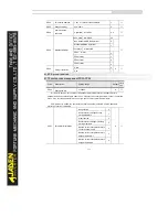
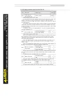
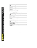
4.19 Control optimization parameters:B5.00-B5.09
Code
Description
Setting range
Default
Restric
tions
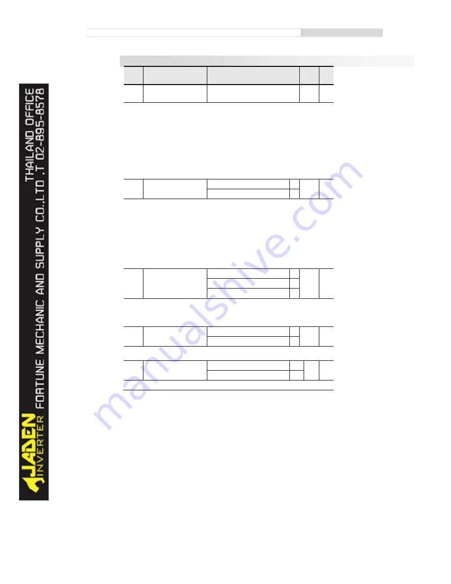
B5.00
DPW M switchover
frequency upper limit
0.00Hz~15.00Hz
12.00Hz
☆
This parameter is valid only for V/F control.
It is used to determine the wave modulation mode in V/F control of asynchronous motor. If the
frequency is lower than the value of this parameter, the waveform is 7-segment continuous
modulation. If the frequency is higher than the value of this parameter, the waveform is 5-segment
intermittent modulation.
The 7-segment continuous modulation causes more loss to switches of the Inverter but smaller
current ripple. The 5-segment intermittent modulation causes less loss to switches of the Inverter
but larger current ripple. This may lead to motor running instability at high frequency. Do not modify
this parameter generally.
For instability of V/F control, refer to parameter P2.11. For loss to Inverter and temperature
rise, refer to parameter P0.15.
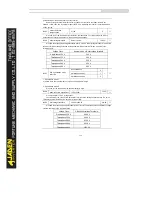
B5.01
PWM modulation mode
Asynchronous modulation
0
0
☆
Synchronous modulation
1
This parameter is valid only for V/F control.
Synchronous modulation indicates that the carrier frequency varies linearly with the change of
the output frequency, ensuring that the ratio of carrier frequency to output frequency remains
unchanged. Synchronous modulation is generally used at high output frequency, which helps
improve the output voltage quality.
At low output frequency (100 Hz or lower), synchronous modulation is not required. This is
because asynchronous modulation is preferred when the ratio of carrier frequency to output
frequency is high.
Synchronous modulation takes effect only when the running frequency is higher than 85 Hz. If
the frequency is lower than 85 Hz, asynchronous modulation is always used.
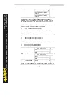
B5.02
Dead zone compensation
mode selection
No compensation
0
1
☆
Compensation mode1
1
Compensation mode2
2
Generally, you need not modify this parameter. Try to use a different compensation mode only
when there is special requirement on the output voltage waveform quality or oscillation occurs on
the motor.
For high power Inverter, compensation mode 2 is recommended.
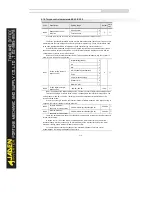
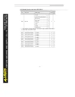
B5.03
Random PW M depth
Random PW M invalid
0
0
☆
Valid
1~10
The setting of random PW M depth can make the shrill motor noise softer and reduce the
electromagnetic interference. If this parameter is set to 0, random PW M is invalid.
B5.04
Rapid current limit
Disabled
0
1
☆
Enabled
1
The rapid current limit function can reduce the Inverter's overcurrent faults at maximum,
Summary of Contents for DLB1-0D40S2G
Page 11: ...11 Graph 1 722 30KW product outline dimensions Graph 1 837 55KW product outline dimensions...
Page 12: ...12 Graph 1 875 110KW product outline dimensions Graph 1 9 132 160KW product outline dimensions...
Page 14: ...14 2 Wirings 2 1 Standard wiring diagrams Graph 2 8 0 4 18 5KW inverter wiring diagram...
Page 15: ...15 Graph 2 922 400KW inverter wiring diagram...
Page 159: ...159...

