-130-
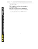
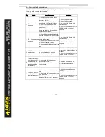
5.2 Common fault and solutions
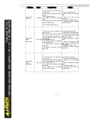
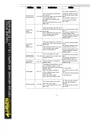
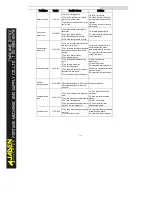
You may come across the following faults during the use of the Inverter. Refer to the
following table for simple fault analysis.
SN
Faul
t
Pos
s
i
bl
e
Caus
es
Sol
ut
i
ons
1
Ther
e
i
s
no
di
s
pl
ay
at
power
-
on.
1:
Ther
e
i
s
no
power
s
uppl
y
t
o
t
he
I
nv
er
t
er
or
t
he
power
i
nput
t
o
t
he
I
nv
er
t
er
i
s
t
oo
l
ow.
2:
The
power
s
uppl
y
of
t
he
s
wi
t
c
h
on
t
he
dr
i
v
e
boar
d
of
t
he
I
nv
er
t
er
i
s
f
aul
t
y
.
3:
The
r
ec
t
i
f
i
er
br
i
dge
i
s
damaged.
4:
The
c
ont
r
ol
boar
d
or
t
he
oper
at
i
on
panel
i
s
f
aul
t
y
.
5:
The
c
abl
e
c
onnec
t
i
ng
t
he
c
ont
r
ol
boar
d
and
t
he
dr
i
v
e
boar
d
and
t
he
oper
at
i
on
panel
br
eak
s
.
1:
Chec
k
t
he
power
s
uppl
y
.
2:
Chec
k
t
he
bus
v
ol
t
age.
3:
Re-
c
onnec
t
t
he
8-
c
or
e
and
28-
c
or
e
c
abl
es
.
4:
Cont
ac
t
t
he
of
f
i
c
i
al
di
s
t
r
i
but
or
or
J
ADEN
di
r
ec
t
l
y
f
or
t
ec
hni
c
al
s
uppor
t
.
2
“
DLB1”
i
s
di
s
pl
ay
ed
at
power
-
on.
1:
The
c
abl
e
bet
ween
t
he
dr
i
v
e
boar
d
and
t
he
c
ont
r
ol
boar
d
i
s
i
n
poor
c
ont
ac
t
.
2:
Rel
at
ed
c
omponent
s
on
t
he
c
ont
r
ol
boar
d
ar
e
damaged.
3:
The
mot
or
or
t
he
mot
or
c
abl
e
i
s
s
hor
t
c
i
r
c
ui
t
ed
t
o
t
he
gr
ound.
4:
The
HALL
dev
i
c
e
i
s
f
aul
t
y
.
5:
The
power
i
nput
t
o
t
he
I
nv
er
t
er
i
s
t
oo
l
ow.
1:
Re-
c
onnec
t
t
he
8-
c
or
e
and
28-
c
or
e
c
abl
es
.
2:
Cont
ac
t
t
he
of
f
i
c
i
al
di
s
t
r
i
but
or
or
J
ADEN
di
r
ec
t
l
y
f
or
t
ec
hni
c
al
s
uppor
t
.
3
23=E.
SHot
i
s
di
s
pl
ay
ed
at
power
-
on.
1:
The
mot
or
or
t
he
mot
or
out
put
c
abl
e
i
s
s
hor
t
-
c
i
r
c
ui
t
ed
t
o
t
he
gr
ound.
2:
The
I
nv
er
t
er
i
s
damaged.
1:
Meas
ur
e
t
he
i
ns
ul
at
i
on
of
t
he
mot
or
and
t
he
out
put
c
abl
e
wi
t
h
a
megger
.
2:
Cont
ac
t
t
he
of
f
i
c
i
al
di
s
t
r
i
but
or
or
J
ADEN
di
r
ec
t
l
y
f
or
t
ec
hni
c
al
s
uppor
t
.
4
The
I
nv
er
t
er
di
s
pl
ay
i
s
nor
mal
upon
power
-
on.
But
“
DLB1”
i
s
di
s
pl
ay
ed
af
t
er
r
unni
ng
and
s
t
ops
i
mmedi
at
el
y
.
1
:
The
c
ool
i
ng
f
an
i
s
damaged
or
l
oc
k
ed-
r
ot
or
oc
c
ur
s
.
2:
The
ex
t
er
nal
c
ont
r
ol
t
er
mi
nal
c
abl
e
i
s
s
hor
t
c
i
r
c
ui
t
ed.
1:
Repl
ac
e
t
he
damaged
f
an.
2:
El
i
mi
nat
e
ex
t
er
nal
f
aul
t
.
5
14=E.
oH1
(
modul
e
ov
er
heat
)
f
aul
t
i
s
r
epor
t
ed
f
r
equent
l
y
.
1:
The
s
et
t
i
ng
of
c
ar
r
i
er
f
r
equenc
y
i
s
t
oo
hi
gh.
2:
The
c
ool
i
ng
f
an
i
s
damaged,
or
t
he
ai
r
f
i
l
t
er
i
s
bl
oc
k
ed.
3:
Component
s
i
ns
i
de
t
he
I
nv
er
t
er
ar
e
damaged
(
t
her
mal
c
oupl
er
or
ot
her
s
)
.
1:
Reduc
e
t
he
c
ar
r
i
er
f
r
equenc
y
(
P0.
15)
.
2:
Repl
ac
e
t
he
f
an
and
c
l
ean
t
he
ai
r
f
i
l
t
er
.
3:
Cont
ac
t
t
he
of
f
i
c
i
al
di
s
t
r
i
but
or
or
J
ADEN
di
r
ec
t
l
y
f
or
t
ec
hni
c
al
s
uppor
t
.
Summary of Contents for DLB1-0D40S2G
Page 11: ...11 Graph 1 722 30KW product outline dimensions Graph 1 837 55KW product outline dimensions...
Page 12: ...12 Graph 1 875 110KW product outline dimensions Graph 1 9 132 160KW product outline dimensions...
Page 14: ...14 2 Wirings 2 1 Standard wiring diagrams Graph 2 8 0 4 18 5KW inverter wiring diagram...
Page 15: ...15 Graph 2 922 400KW inverter wiring diagram...
Page 159: ...159...

