-131-
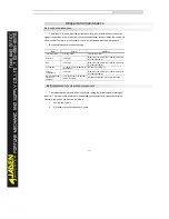
Warning:
※
Do not touch any component inside the device within 5 minutes after the (! CHARGE) light
is off after power off, otherwise user is in danger of electroic shock.
※
Do not touch the PCB or IGBT without electrostatic protections, otherwise the internal
compnents can be damaged.
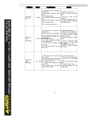
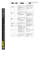
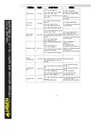
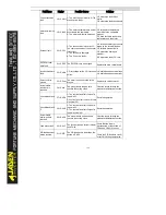
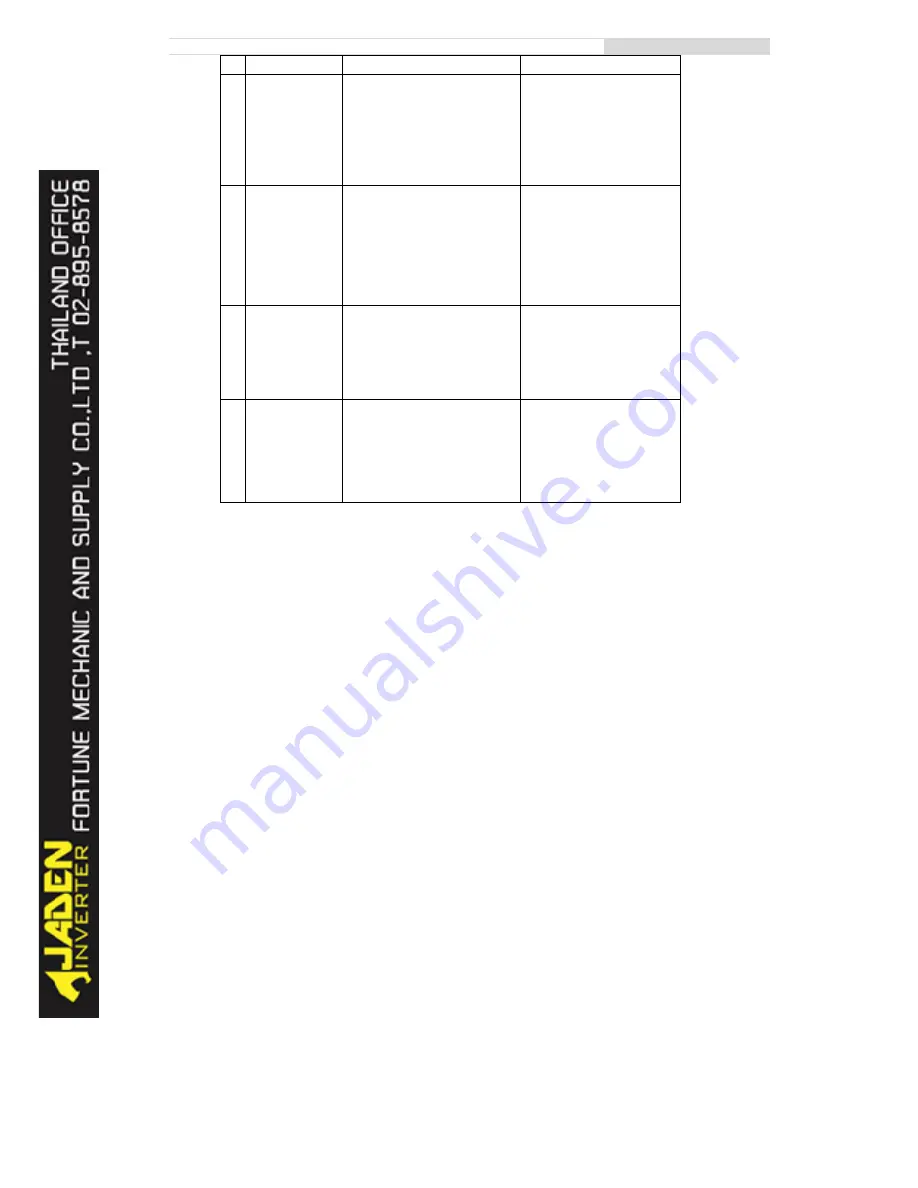
SN
Faul
t
Pos
s
i
bl
e
Caus
es
Sol
ut
i
ons
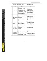
6
The
mot
or
does
not
r
ot
at
e
af
t
er
t
he
I
nv
er
t
er
r
uns
.
1:
Chec
k
t
he
mot
or
and
t
he
mot
or
c
abl
es
.
2:
The
I
nv
er
t
er
par
amet
er
s
ar
e
s
et
i
mpr
oper
l
y
(
mot
or
par
amet
er
s
)
.
3:
The
c
abl
e
bet
ween
t
he
dr
i
v
e
boar
d
and
t
he
c
ont
r
ol
boar
d
i
s
i
n
poor
c
ont
ac
t
.
4:
The
dr
i
v
e
boar
d
i
s
f
aul
t
y
.
1:
Ens
ur
e
t
he
c
abl
e
bet
ween
t
he
I
nv
er
t
er
and
t
he
mot
or
i
s
nor
mal
.
2:
Repl
ac
e
t
he
mot
or
or
c
l
ear
mec
hani
c
al
f
aul
t
s
.
3:
Chec
k
and
r
e-
s
et
mot
or
par
amet
er
s
.
7
The
DI
t
er
mi
nal
s
ar
e
di
s
abl
ed.
1:
The
par
amet
er
s
ar
e
s
et
i
nc
or
r
ec
t
l
y
.
2:
The
ex
t
er
nal
s
i
gnal
i
s
i
nc
or
r
ec
t
.
3:
The
j
umper
bar
ac
r
os
s
SP
and
+24
V
bec
omes
l
oos
e.
4:
The
c
ont
r
ol
boar
d
i
s
f
aul
t
y
.
1:
Chec
k
and
r
es
et
t
he
par
amet
er
s
i
n
gr
oup
P4.
2:
Re-
c
onnec
t
t
he
ex
t
er
nal
s
i
gnal
c
abl
es
.
3:
Re-
c
onf
i
r
m
t
he
j
umper
bar
ac
r
os
s
OP
and
+24
V.
4:
Cont
ac
t
t
he
of
f
i
c
i
al
di
s
t
r
i
but
or
or
J
ADEN
di
r
ec
t
l
y
f
or
t
ec
hni
c
al
s
uppor
t
.
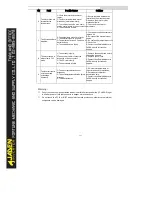
8
The
mot
or
s
peed
i
s
al
way
s
l
ow
i
n
FVC
mode.
1:
The
enc
oder
i
s
f
aul
t
y
.
2:
The
enc
oder
c
abl
e
i
s
c
onnec
t
ed
i
nc
or
r
ec
t
l
y
or
i
n
poor
c
ont
ac
t
.
3:
The
PG
c
ar
d
i
s
f
aul
t
y
.
4:
The
dr
i
v
e
boar
d
i
s
f
aul
t
y
.
1:
Repl
ac
e
t
he
enc
oder
and
ens
ur
e
t
he
c
abl
i
ng
i
s
pr
oper
.
2:
Repl
ac
e
t
he
PG
c
ar
d.
3:
Cont
ac
t
t
he
of
f
i
c
i
al
di
s
t
r
i
but
or
or
J
ADEN
di
r
ec
t
l
y
f
or
t
ec
hni
c
al
s
uppor
t
.
9
The
I
nv
er
t
er
r
epor
t
s
ov
er
c
ur
r
ent
and
ov
er
v
ol
t
age
f
r
equent
l
y
.
1:
The
mot
or
par
amet
er
s
ar
e
s
et
i
mpr
oper
l
y
.
2:
The
ac
c
el
er
at
i
on/
dec
el
er
at
i
on
t
i
me
i
s
i
mpr
oper
.
3:
The
l
oad
f
l
uc
t
uat
es
.
1:
Re-
s
et
mot
or
par
amet
er
s
or
r
e-
per
f
or
m
t
he
mot
or
aut
ot
uni
ng.
2:
Set
pr
oper
ac
c
el
er
at
i
on/
dec
el
er
at
i
on
t
i
me.
3:
Cont
ac
t
t
he
of
f
i
c
i
al
di
s
t
r
i
but
or
or
J
ADEN
di
r
ec
t
l
y
f
or
t
ec
hni
c
al
s
uppor
t
.
Summary of Contents for DLB1-0D40S2G
Page 11: ...11 Graph 1 722 30KW product outline dimensions Graph 1 837 55KW product outline dimensions...
Page 12: ...12 Graph 1 875 110KW product outline dimensions Graph 1 9 132 160KW product outline dimensions...
Page 14: ...14 2 Wirings 2 1 Standard wiring diagrams Graph 2 8 0 4 18 5KW inverter wiring diagram...
Page 15: ...15 Graph 2 922 400KW inverter wiring diagram...
Page 159: ...159...

