-143-
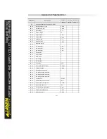
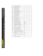
P0.25
Acceleration/Deceleration time base frequency
0
P0.26
Base frequency for UP/DOW N modification
during running
0
P0.27
Binding command source to frequency source
000
P0.28
Communication card type
0
P1
First motor parameters: P1.00-P1.37
P1.00
Motor type selection
0
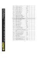
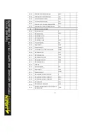
P1.01
Motorrated power
-
P1.02
Motor rated voltage
-
P1.03
Motor rated current
-
P1.04
Motor rated frequency
-
P1.05
Motor rated speed
-
P1.06
Asynchronous motor stator resistance
-
P1.07
Asynchronous motor rotor resistance
-
P1.08
Asynchronous motor leakage inductive reactance
-
P1.09
Asynchronous motor mutual inductive reactance
-
P1.10
Asynchronous motor no load current
-
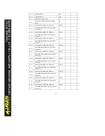
P1.16
Synchronous motor stator resistance
-
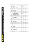
P1.17
Synchronous motor shaft D inductance
0.00Hz
P1.18
Synchronous motor shaft Q inductance
0.0%
P1.19
Inductance resistance unit
0.0%
P1.20
Back EMF coefficient
0.1V
P1.21
Phase loss detection time
0
P1.27
Encoder pulse per revolution
2500
P1.28
Encoder type
0
P1.30
A/B phase sequence of ABZ incremental encoder
0
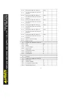
P1.31
Encoder installation angle
0.00
P1.32
U, V, W phase sequence of UVW encoder
0
P1.33
UVW encoder angle offset
0.00
P1.34
Resolver pole pairs
1
P1.35
UVW pole pairs
4
P1.36
Encoder wire-break fault detection time
0.0s
P1.37
Auto-tuningselection
0
P2
V/F control parameters:P2.00-P2.15
P2.00
V/F curve setting
0
P2.01
Torque boost
-
P2.02
Torque boost cut-off frequency
50.00Hz
Summary of Contents for DLB1-0D40S2G
Page 11: ...11 Graph 1 722 30KW product outline dimensions Graph 1 837 55KW product outline dimensions...
Page 12: ...12 Graph 1 875 110KW product outline dimensions Graph 1 9 132 160KW product outline dimensions...
Page 14: ...14 2 Wirings 2 1 Standard wiring diagrams Graph 2 8 0 4 18 5KW inverter wiring diagram...
Page 15: ...15 Graph 2 922 400KW inverter wiring diagram...
Page 159: ...159...


