-147-
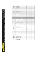
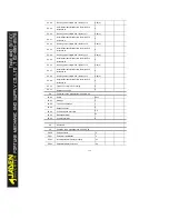
P6.03
Startup frequency
0.00Hz
P6.04
Startup frequency holding time
0.0s
P6.05
Startup DC braking current/Pre-excited current
0%
P6.06
Startup DC braking time/Pre-excited time
0.0s
P6.07
Acceleration/deceleration mode
0
P6.08
Time proportion of S-curve start segment
30.0%
P6.09
Time proportion of S-curve end segment
30.0%
P6.10
Stop mode
0
P6.11
Initial frequency of stop DC braking
0.00Hz
P6.12
Waiting time of stop DC braking
0.0s
P6.13
Stop DC braking current
0%
P6.14
Stop DC braking time
0.0s
P6.15
Brake use ratio
100%
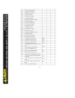
P7
Operation panel and display:P7.00-P7.14
P7.01
DIR/JOG function
0
P7.02
STOP/RESET
1
P7.03
LED display running parameters 1
1F
P7.04
LED display running parameters 2
0
P7.05
LEDdisplay stopparameters
33
P7.06
Load speed display coefficient
1.0000
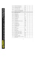
P7.07
Heatsink temperature of inverter module
12
℃
P7.08
Rectification module temperature
0
℃
P7.09
Accumulativerunning time
0h
P7.10
Product number
-
P7.11
Software version
-
P7.12
Number of decimal places for load speed display
1
P7.13
Accumulative power-on time
-
P7.14
Accumulative power consumption
-
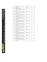
P8
Auxiliary functions: P8.00-P8.53
P8.00
JOG running frequency
2.00Hz
P8.01
JOG acceleration time
20.0s
P8.02
JOG deceleration time
20.0s
P8.03
Acceleration time 2
10.0s
P8.04
Deceleration time 2
10.0s
P8.05
Acceleration time 3
10.0s
Summary of Contents for DLB1-0D40S2G
Page 11: ...11 Graph 1 722 30KW product outline dimensions Graph 1 837 55KW product outline dimensions...
Page 12: ...12 Graph 1 875 110KW product outline dimensions Graph 1 9 132 160KW product outline dimensions...
Page 14: ...14 2 Wirings 2 1 Standard wiring diagrams Graph 2 8 0 4 18 5KW inverter wiring diagram...
Page 15: ...15 Graph 2 922 400KW inverter wiring diagram...
Page 159: ...159...


